Insert for a rollout type waste container and waste container assembly

Active Publication Date: 2004-04-22
SCHAEFER SUBCO LLC
View PDF5 Cites 42 Cited by
  • Summary
  • Abstract
  • Description
  • Claims
  • Application Information

AI Technical Summary

Benefits of technology

[0047] As is shown in FIG. 1, a recessed relief 18 area is formed in each of four lower corners 19 of the insert bin 10 adjacent the floor 11. The relief areas 18 provide enhanced stability and strength to the insert bin 10, which in turn enhances the ability of the insert bin 10 to return to its original shape after deforming in response to the bending and twisting forces typically applied to a waste cart by a hydraulic lift during the waste collection and removal process. The relief areas 18 are also shaped so that the exterior of the insert bin 10 conforms to the interior walls of the refuse compartment of a waste cart. As is described more fully below with reference to FIG. 4, the shape of the relief areas 18 permits the insert bin 10 to be nested within the interior of the waste cart. Referring again to FIG. 1, the forward wall 14 of the insert bin 10 also includes a ledge structure 20 defining a shoulder 21 which extends into the interior of the insert bin 10. The inwardly-directed shape of the shoulder 21 is also shown in FIG. 2, and permits the ledge structure 20 of the insert bin 10 to be superposed upon an identical ledge structure of a waste cart.
[0050] Although the first and second housings 22 and 23 may have any suitable dimensions, as is shown in FIG. 1, the first housing 22 preferably has a length "L1" that is greater than the length "L2" of the second housing 23. As described below with reference to FIGS. 6 through 8, varying the lengths of the first and second housings 22 and 23 in this manner increases the relative speed and ease with which the insert bin 10 may be locked into place relative to the waste container.
[0053] Referring now to FIG. 5, the insert bin 10 is moved into place within the interior of the waste cart 29 by applying downward pressure to the insert bin 10 in the direction "D" shown until a top return flange 43 of the insert bin 10 is seated over a vertically-extending flange 44 of the waste cart 29. The vertical flange 44 extends around the mouth of the waste cart 29 and cooperates with a complementary-shaped groove 45 defined by the top return flange 43 on the insert bin 10 to seal off the interior of the waste cart 29 from debris that would otherwise get caught between the exterior sidewalls of the insert bin 10 and the interior sidewalls of the waste cart 29. As is shown in FIG. 5, the length "L" of the groove 45 is less than the height "H" of the vertical flange 44 of the waste cart 29. This allows the insert bin 10 to seat itself completely on the vertical flange 44, insuring the correct movement of the insert bin 10 allowed by the lock bar attachment method, which further inhibits passage of debris and liquid into the interior of the cart 29.
[0054] Referring now to FIG. 6, once the top return flange 43 is seated over the vertical flange 44 of the waste cart 29, the lock bar 38 is installed by inserting the first end 46 of the bar 38 through one of the openings 42 in the lateral wall 40 of the ledge structure 37 on the waste cart 29 in the direction "D" shown. As is shown in FIG. 7, inserting the first end 46 of the lock bar 38 into the deeper of the two housings 22 causes the second end 47 of the lock bar 38 to move past the opposite lateral wall 39 toward the center of the ledge structure 37. This in turn permits the second end 47 of the lock bar 38 to be inserted through the other opening 41 and into the second housing 23 in the insert bin 10. This is possible because the pre-selected length P of the lock bar 38 is shorter than the horizontal distance W between the end surface 28 of the first housing 22 and the lateral wall 41.

Problems solved by technology

Although alternative methods and devices exist to reduce the volume of refuse collected by waste haulers, such methods and devices are often cost-prohibitive for waste haulers to use.
For example, while a waste hauler could elect to purchase and distribute waste carts with 20 gallon interiors in response to a governmental regulation requiring that a 35 gallon interior be reduced by 15 gallons, such a purchase would be impractical if the service area of the waste hauler extended across a district not subject to the 20 gallon restriction.
While insert bins are currently available in the marketplace, the bins are inadequate because they use mechanical fasteners to retain the bin in place within respective waste carts.
Regardless of whether mechanical fasteners or press-fitting is employed, prior art bins often fail in the field.
For those insert bins that are press fit in place within the interiors of waste carts, the distortion the waste cart suffers during the waste collection process can cause separation between the waste cart and the insert bin, which in turn breaks the vacuum and allows the insert bin to slide out of the interior as refuse is being emptied into the truck.
Furthermore, the waste cart and insert bin usually differ from one another with respect to the manufacturing processes, wall thicknesses or materials used--any one of these differences will cause a differential in shrinkage or expansion of the insert bin and waste cart when they are exposed to hot or cold temperatures.
This differential can nullify the press fit and cause the insert bin to separate from and ultimately slide out of the waste cart.

Method used


Image

  • Insert for a rollout type waste container and waste container assembly
  • Insert for a rollout type waste container and waste container assembly
  • Insert for a rollout type waste container and waste container assembly

Examples


Embodiment Construction

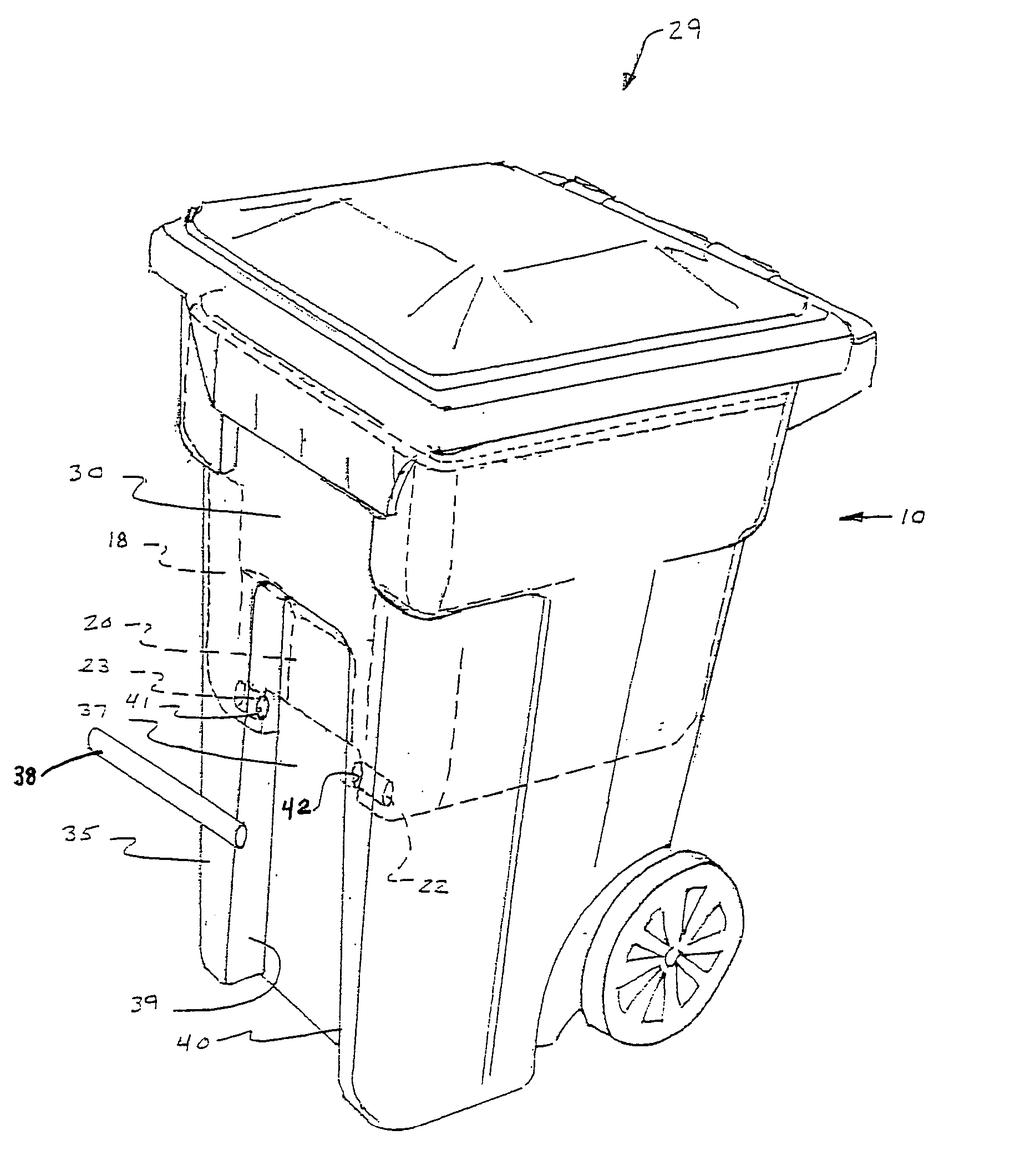
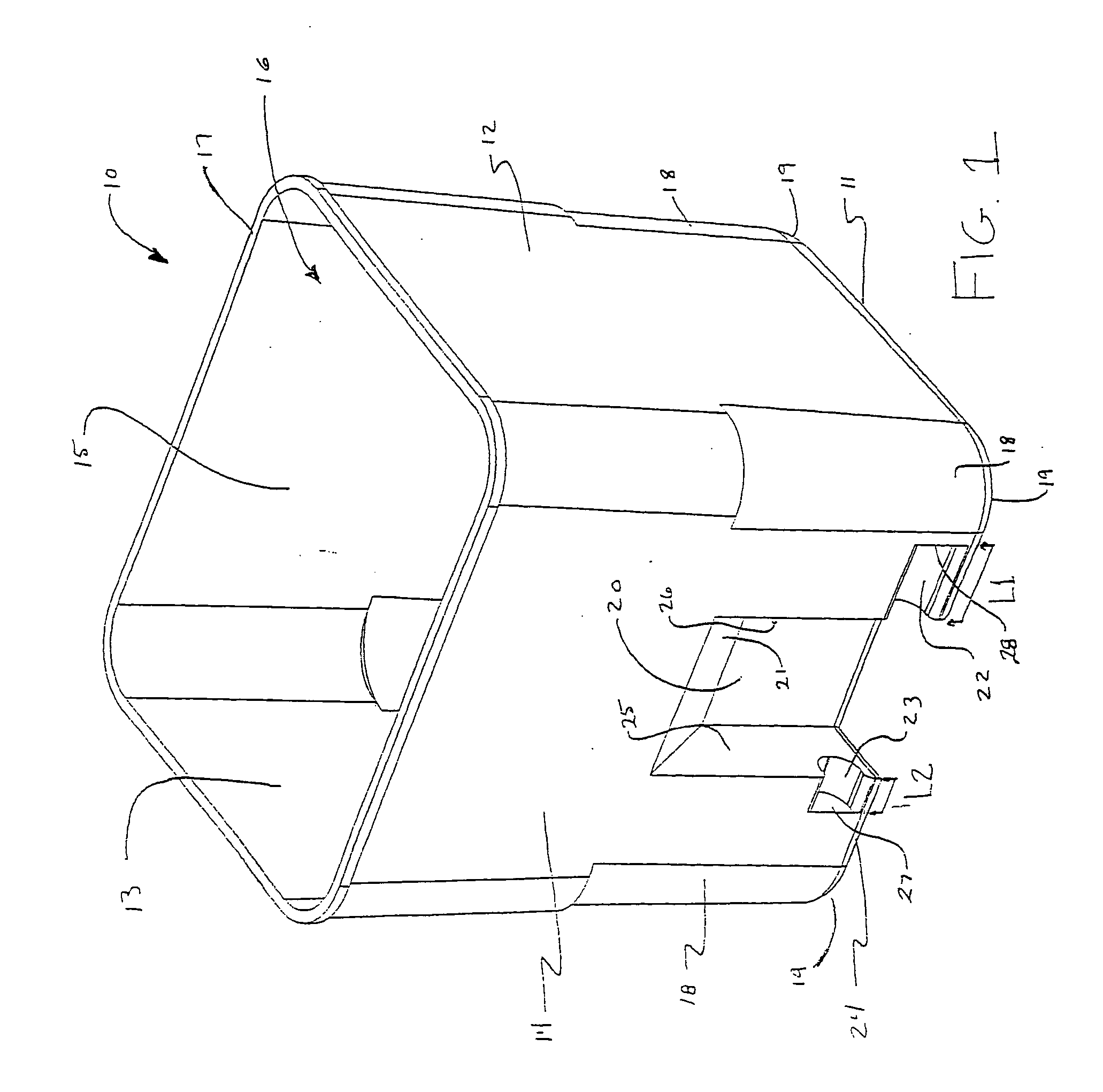
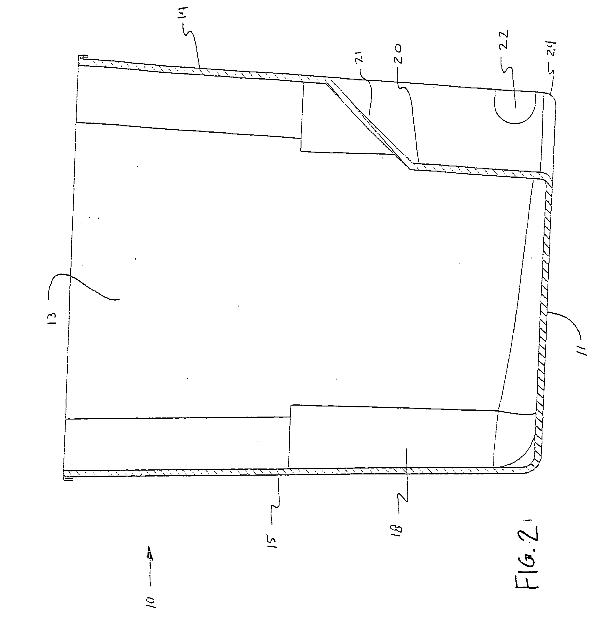
[0046] Referring now specifically to the drawings, an insert bin shown generally at 10 according to one preferred embodiment of the invention is shown in FIG. 1. The insert bin includes a floor 11 upon which two opposing sidewalls 12 and 13, a forward wall 14, and an opposing rear wall 15 are formed, thereby defining an interior 16. As described more fully below, the interior 16 of the insert bin 10 functions as a reduced-volume refuse compartment when the insert bin 10 is positioned within the refuse compartment of a conventional rollout type waste container (hereafter referred to interchangeably as a "waste container" or "waste cart"). The forward wall 14, rear wall 15 and major opposing sidewalls 12 and 13 terminate in upper edges which form a continuous rim 17 defining a mouth of the insert bin 10.

[0047] As is shown in FIG. 1, a recessed relief 18 area is formed in each of four lower corners 19 of the insert bin 10 adjacent the floor 11. The relief areas 18 provide enhanced stab...


PUM


Abstract

An insert bin for use with a rollout type waste container or cart. The insert bin limits the volume of refuse or recyclable material that a customer may deposit in the container. The insert bin is held in place within the interior of a waste cart without the use of separate mechanical components or a press fit. The insert bin instead takes advantage of the lift bar, which already exists on a waste cart providing a bin that is strong and easily attached to a waste container or cart.

Description

[0001] This application claims the benefit of Provisional Application No. 60 / 418,382 filed on Oct. 15, 2002.TECHNICAL FIELD AND BACKGROUND OF THE INVENTION[0002] This invention relates to an insert bin for use with a rollout type waste container or cart. In the waste industry, insert bins are customarily used by waste haulers to reduce the interior volume of rollout waste containers, which likewise limits the volume of refuse or recyclable material that a customer may deposit in the container in between waste collection pick-ups by the waste hauler.[0003] Although alternative methods and devices exist to reduce the volume of refuse collected by waste haulers, such methods and devices are often cost-prohibitive for waste haulers to use. For example, while a waste hauler could elect to purchase and distribute waste carts with 20 gallon interiors in response to a governmental regulation requiring that a 35 gallon interior be reduced by 15 gallons, such a purchase would be impractical i...

Claims


Application Information

Patent Timeline
IPC IPC(8): B65F1/04
CPCB65F2210/183B65F1/04
Inventor MCDADE, CLINTONMARLOW, MORRIS
Owner SCHAEFER SUBCO LLC
Why Eureka
Try Eureka