
Data copying system, relaying device, data transfer/reception system and program for copying of data in storage unit

a data copying and data transfer technology, applied in the field of data copying systems, relaying devices, data transfer/reception systems and program for copying data in storage units, can solve the problems of reducing the efficiency of data copying,

Active Publication Date: 2004-03-04
RAKUTEN GRP INC
View PDF37 Cites 51 Cited by
  • Summary
  • Abstract
  • Description
  • Claims
  • Application Information

AI Technical Summary

Benefits of technology

[0011] In transmitting data from the normal system via a relaying device to a standby system, the following problem is encountered. The relaying device sends data received from a normal system to a standby system and, on receipt of a notice on the completion of reception from the standby system, notifies the effect of the completion of transmission to the normal system. The normal system does not switch to the next processing unless it receives a notice on the completion of transmission from the relaying device. As a result, considerable time is needed since data transfer from the normal system to the relaying device until start of the next processing. In particular, should a relaying device or a standby system be provided as measures against possible breakout of disasters, the relaying device is provided in a place remote from the normal system, whilst a standby system is provided in a still more remote place. As a result, considerable time is needed for transmitting / receiving data or notices between the normal system and the relaying device or between the relaying device and the standby system, thus retarding the start of the next operation in the normal system.
[0013] Moreover, if data is discarded in terms of a data transfer unit, such as a packet, in the data transfer process, the storage unit of the normal system, as a source of transmission, has to re-transmit data. That is, more time is taken until completion of the data transfer, thus further retarding the start of the next operation.
[0014] In addition, if data backup operations are carried out from the normal system to the standby system, the amount of data to be transferred is increased, in addition to the data transfer distance being extremely long, thus further protracting the time for transmission.
[0019] The relaying device in accordance with another aspect of the present invention includes non-volatile storage means for storing a command and data received from the first storage unit and relaying processing means for relay controlling the data. The relaying processing means may cause the command and the data received from the first storage unit to be stored in the non-volatile storage means and transmit the so stored command and data at an optional timing to the second storage unit. With this configuration, it is possible to reduce the management cost of the communication cost of a communication network interconnecting the relaying device and the second storage unit.
[0032] In the data copying system according to the present invention, for example, the redundancy processing means in the first storage unit divides the original data into divided data and creates redundant data enabling restoration of the original data even on erasure of one or more of the divided data.
[0042] In the data copying system according to the present invention, when an abnormality has occurred in an operation system, the snap shot forming means in the storage unit of the standby system frees the area of the recording medium, where data has been stored after forming the directly previous snap shot, to a non-use state, to restore the stored information to the state at the time of forming the directly previous snap shot.

Problems solved by technology

In transmitting data from the normal system via a relaying device to a standby system, the following problem is encountered.
As a result, considerable time is needed since data transfer from the normal system to the relaying device until start of the next processing.
As a result, considerable time is needed for transmitting / receiving data or notices between the normal system and the relaying device or between the relaying device and the standby system, thus retarding the start of the next operation in the normal system.
In addition, if data backup operations are carried out from the normal system to the standby system, the amount of data to be transferred is increased, in addition to the data transfer distance being extremely long, thus further protracting the time for transmission.

Method used


Image

  • Data copying system, relaying device, data transfer/reception system and program for copying of data in storage unit
  • Data copying system, relaying device, data transfer/reception system and program for copying of data in storage unit
  • Data copying system, relaying device, data transfer/reception system and program for copying of data in storage unit

Examples


embodiment 1

[0093] Embodiment 1

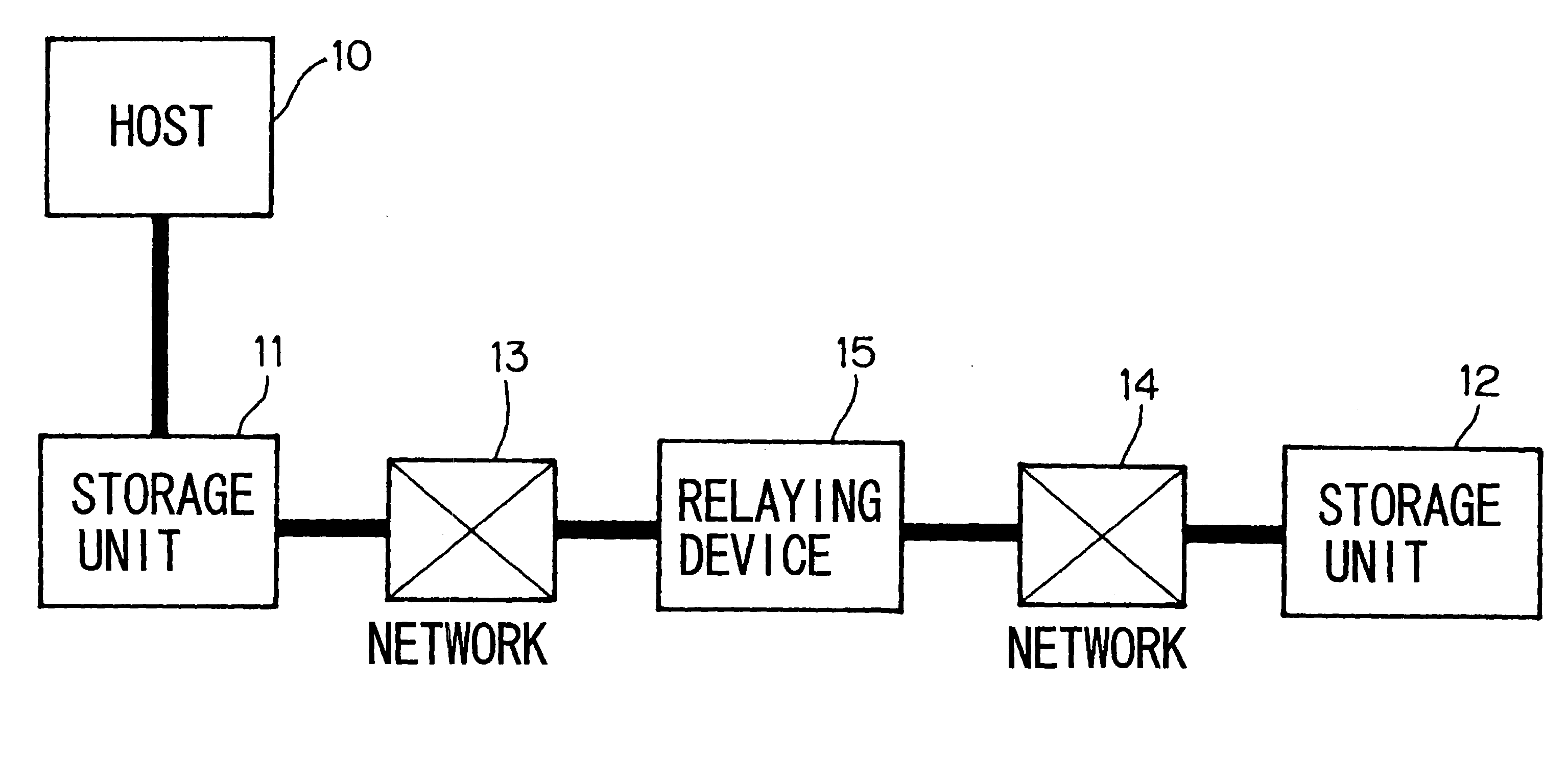
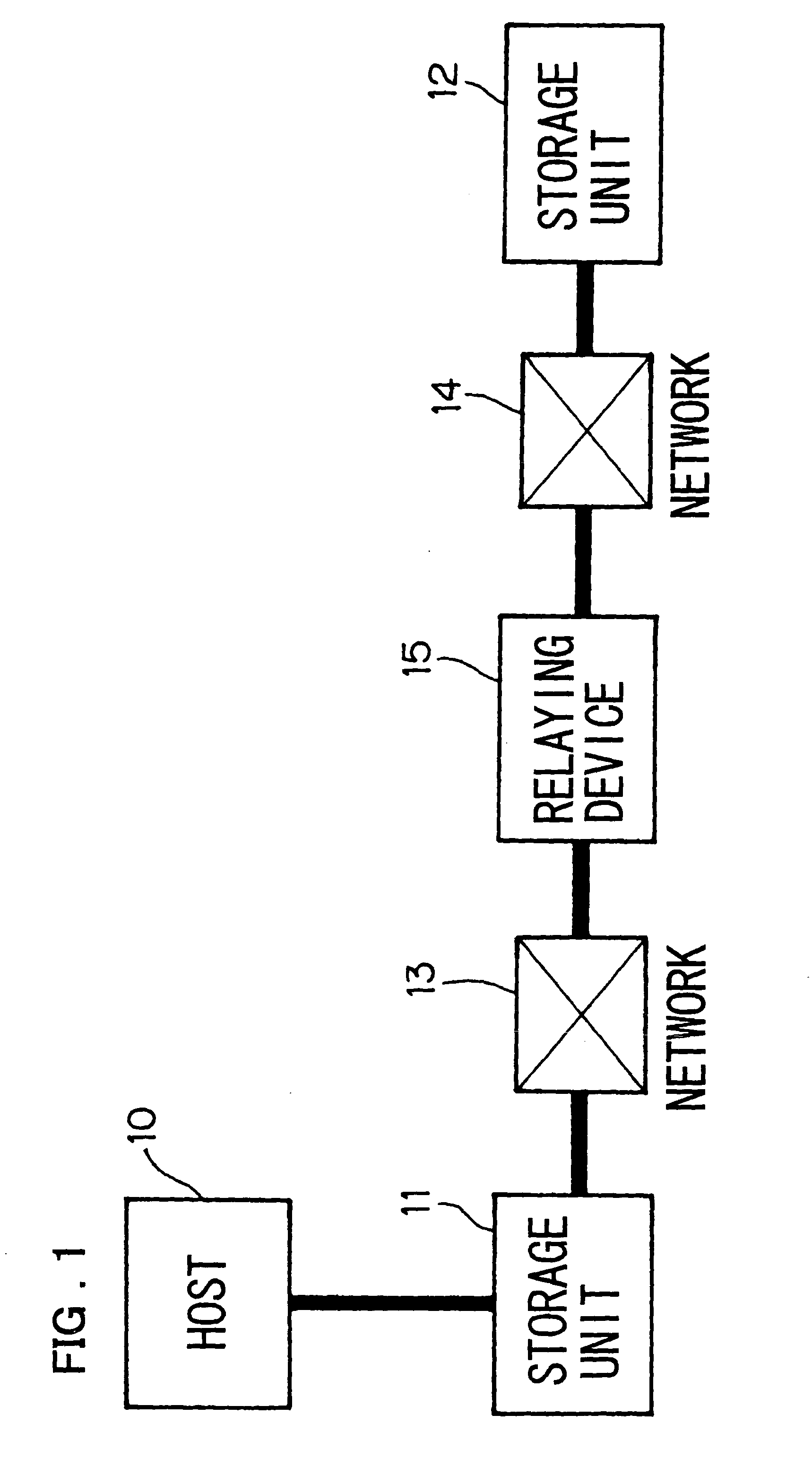
[0094] FIG. 1 is a block diagram of showing a configuration of a data copying system according to a first embodiment of the present invention. In the data copying system, shown in FIG. 1, a storage unit 11 is locally connected to a host 10 (host computer) which utilizes the storage unit 11. The storage unit 11 is connected to a relaying device 15 over a communication network (referred to below as network) 13, such as the Internet or a leased line. The relaying device 15 is connected over a network 14 to a storage unit 12.

[0095] The storage units 11 and 12 may, for example, be each a unit magnetic disc device, a unit optical disc device or a unit magneto-optical disc device. As the storage units 11 and 12, a disc array device, which is a set of unit magnetic disc devices, unit optical disc devices or unit magneto-optical disc devices, may be used. The host 10 and the storage unit 11 are interconnected by for example the SCSI, Fiber channel or Ethernet (registered t...

embodiment 2

[0123] Embodiment 2

[0124] In the first embodiment, the relaying device 15 starts data transfer to the storage unit 12 after receiving the totality of one-block data from the storage unit 11. Alternatively, the relaying device 15 may start data transfer to the storage unit 12 without awaiting the completion of reception of one-block data from the storage unit 11. FIG. 6 depicts a flowchart showing the operation of the relaying processor 151 in the second embodiment which manages control to commence data transfer to the storage unit 12 without awaiting the completion of the data reception from the storage unit 11. Meanwhile, the structure of the data copying system, storage units 11 and 12 and the relaying device 15 is the same as that of the first embodiment (see FIGS. 1 to 3).

[0125] The relaying processor 151 receives the write command, sent by the storage unit 11 in the step S101, as in the first embodiment described above. The relaying device 15 then acquires an area necessary for...

embodiment 3

[0130] Embodiment 3

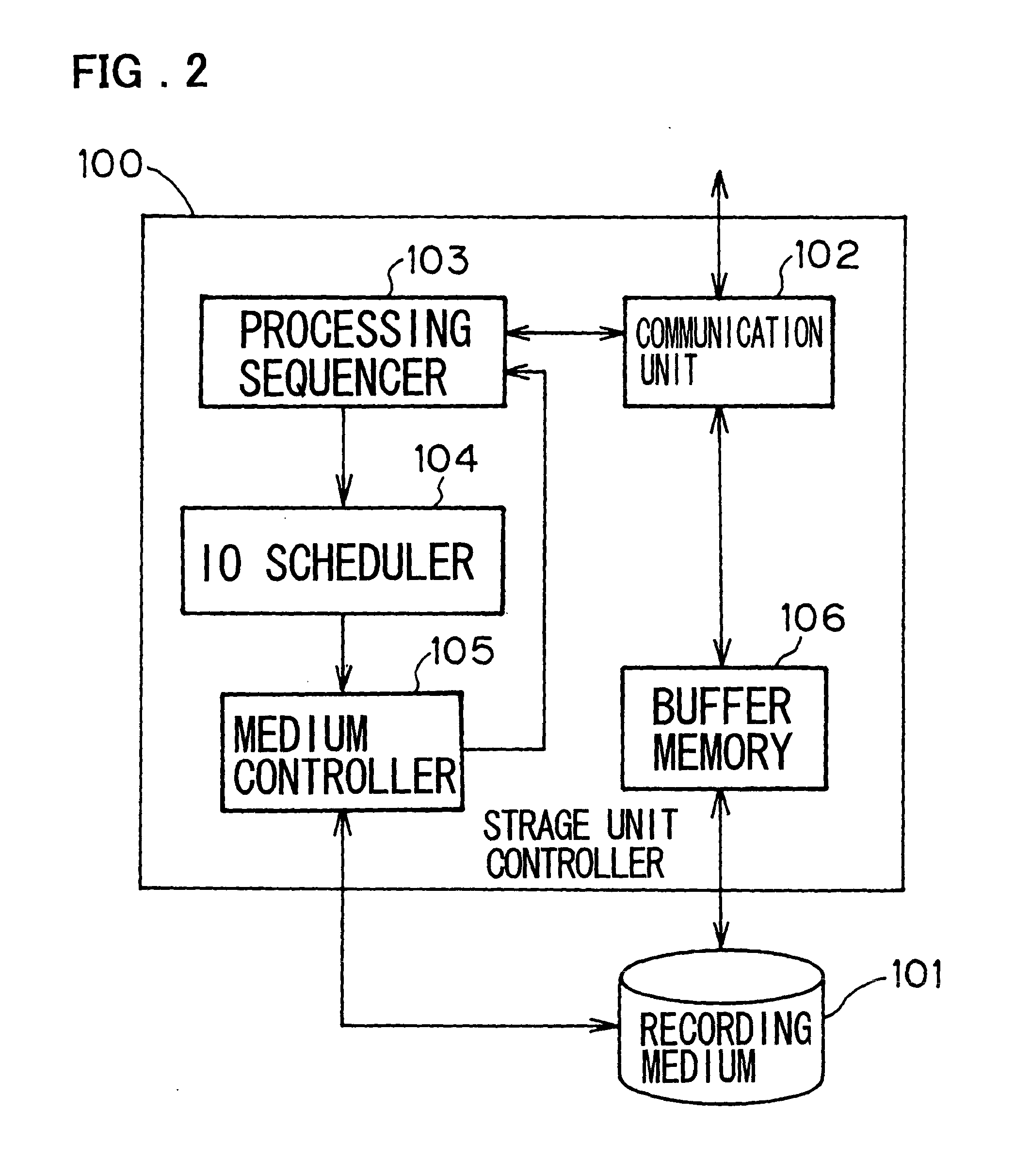
[0131] In the first and second embodiments, data backup for the storage unit 11 is realized. The data of the storage unit 11 may, however, be transferred by mirroring to the storage unit 12. FIG. 7 depicts a flowchart showing the operation of the processing sequencer 103 in the storage unit 11 in the storage unit controller 100 in a third embodiment, that is, in case of effecting the mirroring. Meanwhile, the configuration of the data copying system, storage units 11 and 12 and the relaying device 15 is the same as that of the first embodiment (see FIGS. 1 to 3). Moreover, in the storage unit 11, the operation of the communication unit 102, IO scheduler 104 and the medium control unit 105 is the same as that in the first embodiment.

[0132] The backup shown in the first and second embodiments is commenced on the occasion of the host 10 issuing a copy command to the storage unit 11. The mirroring of the third embodiment is commenced on the occasion of the host issuin...


PUM


Abstract

A relaying device for relaying data transferred from first storage unit to a second storage unit, is provided outside a range presumed to be affected by a disaster, when a disaster, such as an earthquake, has broken out in an installation site of a host of a normal system (host computer) and the first storage unit. Moreover, the relaying device is placed at such a location that the data transfer time between the first storage unit and the relaying device is shorter than the data transfer time in case the first and second storage units directly transfer data with each other. On receipt of data from the first storage unit, the relaying device notifies the first storage unit of the completion of reception of the data before completing transmission of the data to the second storage unit.

Description

[0001] This invention relates to a data copying system, a relaying device, a data transfer / reception system and a program for copying of data in a storage unit[0002] Such a computer system has already been realized which is provided with a normal system (a working system) and a standby system in order to maintain the functions of the computer system even in case of a disaster. For example, the EMC Corporation has developed a system which effects mirroring using a normal storage unit system and a standby storage unit system. The information concerning such system is disclosed on the Internet in the URL of "http: / / www.emc2.co.jp / local / ja / JP / products / produc-t_pdfs / srdf / srdf.pdf".[0003] In Japanese Patent Kokai Publication JP-P2000-305856A, there is disclosed a system which achieves a dual data system between a main center (normal system) and a remote center (stand-by system).[0004] In a normal system, in general, a storage unit of a normal system and a host computer of the normal syste...

Claims


Application Information

Patent Timeline
Patent Type & Authority Applications(United States)
IPC IPC(8): G06F13/12G06F3/06G06F7/00G06F12/00G06F13/00
CPCG06F11/1456G06F11/1469G06F11/2097G06F11/2069
Inventor YAMATO, JUN-ICHIKIKUCHI, YOSHIHIDEKANEKO, YUJI
Owner RAKUTEN GRP INC
Learn More