Mouse hole support unit with rotatable or stationary operation

Inactive Publication Date: 2008-08-28
XTECH INDS
View PDF23 Cites 25 Cited by
  • Summary
  • Abstract
  • Description
  • Claims
  • Application Information

AI Technical Summary

Benefits of technology

[0013]The present invention provides improved methods and apparatus for supporting and engaging drill pipe in a mouse hole that allows for multiple drill pipe sections or joints to be attached together before being attached to an existing drill string. The present invention is designed to allow for engagement and disengagement of drill pipe sections of various diameters without the need for manually inserting or removing support shims or slips. These features allow for speedy set up and attachment of drill pipe sections during drilling operations. The support unit of the present invention is also portable, and may be retrofitted into an existing drill rig platform.
[0014]Embodiments of the present invention allow for the connection of multiple sections of drill pipe in a mouse hole by securing a given section of pipe in the hole and delivering a rotational force to secure that pipe section to another section of drill pipe placed above it over the mouse hole. In some embodiments, the rotational force may be provided by the support unit of the present invention. In alternative embodiments, the rotational force may be provided by an outside source such as an iron roughneck, with the support unit of the present invention holding the drill pipe section in a stationary position as such force is delivered. The unit then allows the connected pipe sections to be lowered and secured so the process can be repeated to connect multiple sections of drill pipe together in the mouse hole. The multiple sections of drill pipe may then be retrieved as a unit, and attached to the pipe string already being used to drill the well. This saves considerable time when extending the length of the main drill pipe string. Instead of attaching a single section of pipe to the main pipe string each time, the present invention allows for a pre-connected set of multiple pipe sections to be attached. Thus, for example, if the set in the mouse hole is made up of three attached pipe sections, the time for drilling the same depth may be speeded up by much as two thirds.

Problems solved by technology

This saves considerable time when extending the length of the main drill pipe string.

Method used


Image

  • Mouse hole support unit with rotatable or stationary operation
  • Mouse hole support unit with rotatable or stationary operation
  • Mouse hole support unit with rotatable or stationary operation

Examples


Embodiment Construction

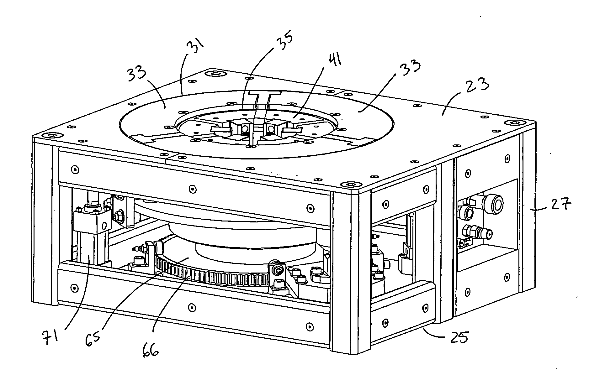
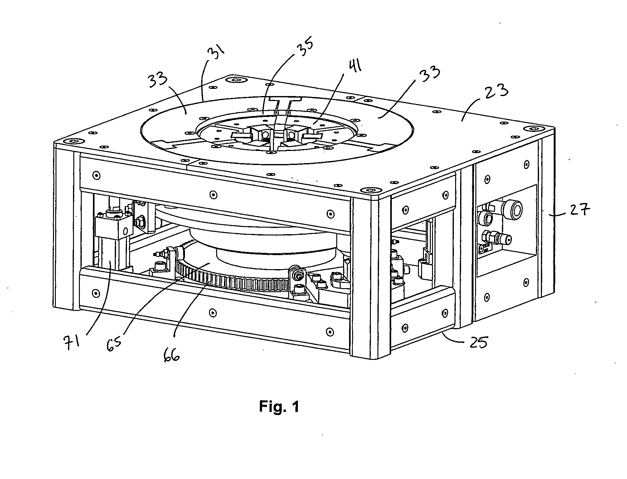
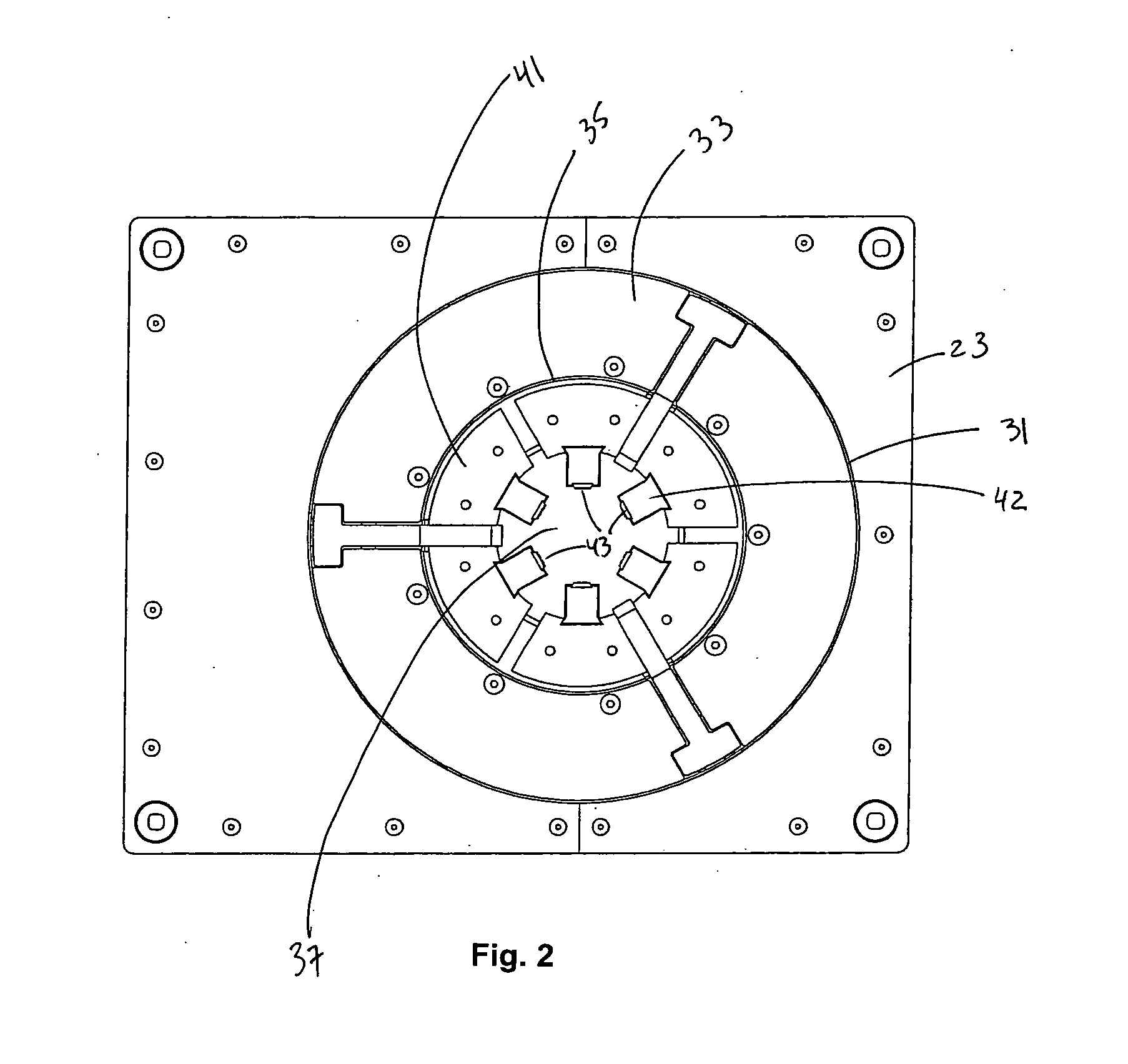
[0062]Referring to the drawings wherein like reference characters designate like or corresponding parts throughout the several views, and referring particularly to the illustrated embodiments of FIGS. 1-10, it is seen that the illustrated embodiment of the present invention includes a frame 21 having an upper surface 23 and a lower surface 25 separated by a plurality of supports 27. Frame 21 is designed for placement above a mouse hole of a drilling rig. The depth of the mouse hole should be sufficient to accommodate the desired number of pipe sections to be attached together as a unit prior to installation in the main pipe string of the drilling rig. Frame 21 may be installed such that the lower surface 25 rests upon the existing floor of a drill rig, or upon the floor surrounding the mouse hole. Alternatively, frame 21 may be installed such that upper surface 23 is flush with or below the floor of the drill rig or mouse hole. In several embodiments, frame 21 and the components pro...


PUM


Abstract

The present invention provides improved methods and apparatus for supporting and engaging drill pipe in a mouse hole that allows for multiple drill pipe sections to be attached together before being attached to an existing drill string. The present invention is designed to allow for engagement and disengagement of drill pipe sections of various diameters without the need for manually inserting or removing support shims or slips. Embodiments of the invention provide for rotation of the engaged drill pipe sections to assist in connection to another drill pipe section. These features allow for speedy set up and attachment of drill pipe sections during drilling operations. The support unit of the present invention is also portable, and may be retrofitted into an existing drill rig platform.

Description

[0001]This application claims the benefit of U.S. Provisional Application No. 60 / 903,699 filed on Feb. 27, 2007, and U.S. Provisional Application No. 60 / 903,721 filed on Feb. 27, 2007, both of which are incorporated herein by this reference in their entirety.BACKGROUND OF THE INVENTION[0002]1. Field of the Invention[0003]The present invention relates to methods and apparatus for use with a shallow bore hole under the floor of a drilling rig in which sections of drill pipe are temporarily placed before being connected to the drill assembly, and more particularly to methods and apparatus for supporting drill pipe sections in a house hole adjacent to a drilling rig.[0004]2. Description of the Prior Art[0005]Drilling rigs are designed to drill wells deep into the earth's surface in order to extract materials such as oil, gas, etc. In order to drill effectively a great distance, the drill pipe consists of sections or “joints” of drill pipe or tubing which are continuously attached togeth...

Claims


Application Information

Patent Timeline
IPC IPC(8): E21B19/06
CPCE21B19/10E21B19/16E21B19/14
Inventor ANTHONY, PAUL
Owner XTECH INDS
Why Eureka
Try Eureka