
Device for connecting component parts, comprising a blind rivet fastener

Active Publication Date: 2007-06-05
BOLLHOFF VERBINDUNGSTECHNIK GMBH
View PDF18 Cites 26 Cited by
  • Summary
  • Abstract
  • Description
  • Claims
  • Application Information

AI Technical Summary

Benefits of technology

[0005]It is an object of the invention to provide a device of the type indicated above, which can be mounted more easily and efficiently.
[0008]It is a particular advantage that the spacer and the blind rivet nut can be supplied in a condition in which they are already screwed together. Thus, on behalf of the user, the mounting step of inserting and screwing-in the spacer into the blind rivet nut may be dispensed with. This substantially simplifies the mounting process and leads to considerable time and cost savings.
[0015]In its active position, the intermediate member is preferably locked by snap-action against axial displacement in the spacer. The snap-action assures a defined position in the spacer. In particular, this prevents the intermediate member from being loosened or pushed out of its active position when the two component parts, once they have been connected, are disassembled and then the connecting screw is inserted once again.
[0017]Preferably, the blind rivet nut forms a support surface for one end of the intermediate member. This has the advantage that, when the blind rivet nut has been riveted and then the connecting screw is inserted into the spacer, the intermediate member may be supported on the support surface. This efficiently prevents the intermediate member from being pushed out of the spacer, and this effect may additionally be assisted by the snap-mechanism mentioned above.
[0019]It is preferable for both embodiments that the device has a stop mechanism which limits the screwing-in movement of the blind rivet nut and the spacer. This stop mechanism then prevents the spacer from being tightened too fast to the blind rivet nut when, after the blind rivet nut has been riveted, the threaded stud is screwed out. Otherwise, the tightening of the spacer could later prevent the spacer from being screwed out due to the frictional connection, as intended.

Problems solved by technology

This substantially simplifies the mounting process and leads to considerable time and cost savings.

Method used


Image

  • Device for connecting component parts, comprising a blind rivet fastener
  • Device for connecting component parts, comprising a blind rivet fastener
  • Device for connecting component parts, comprising a blind rivet fastener

Examples


Embodiment Construction

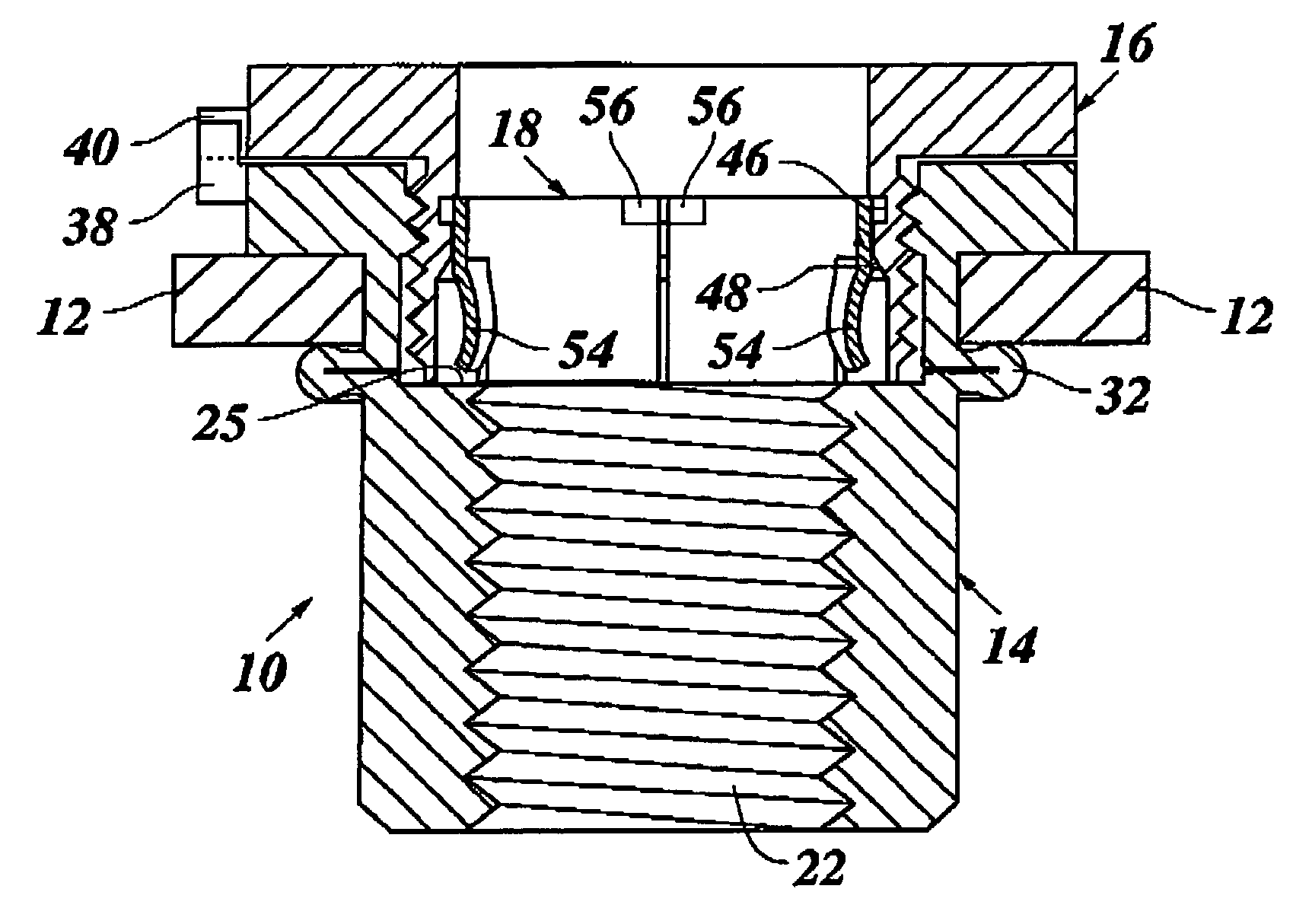
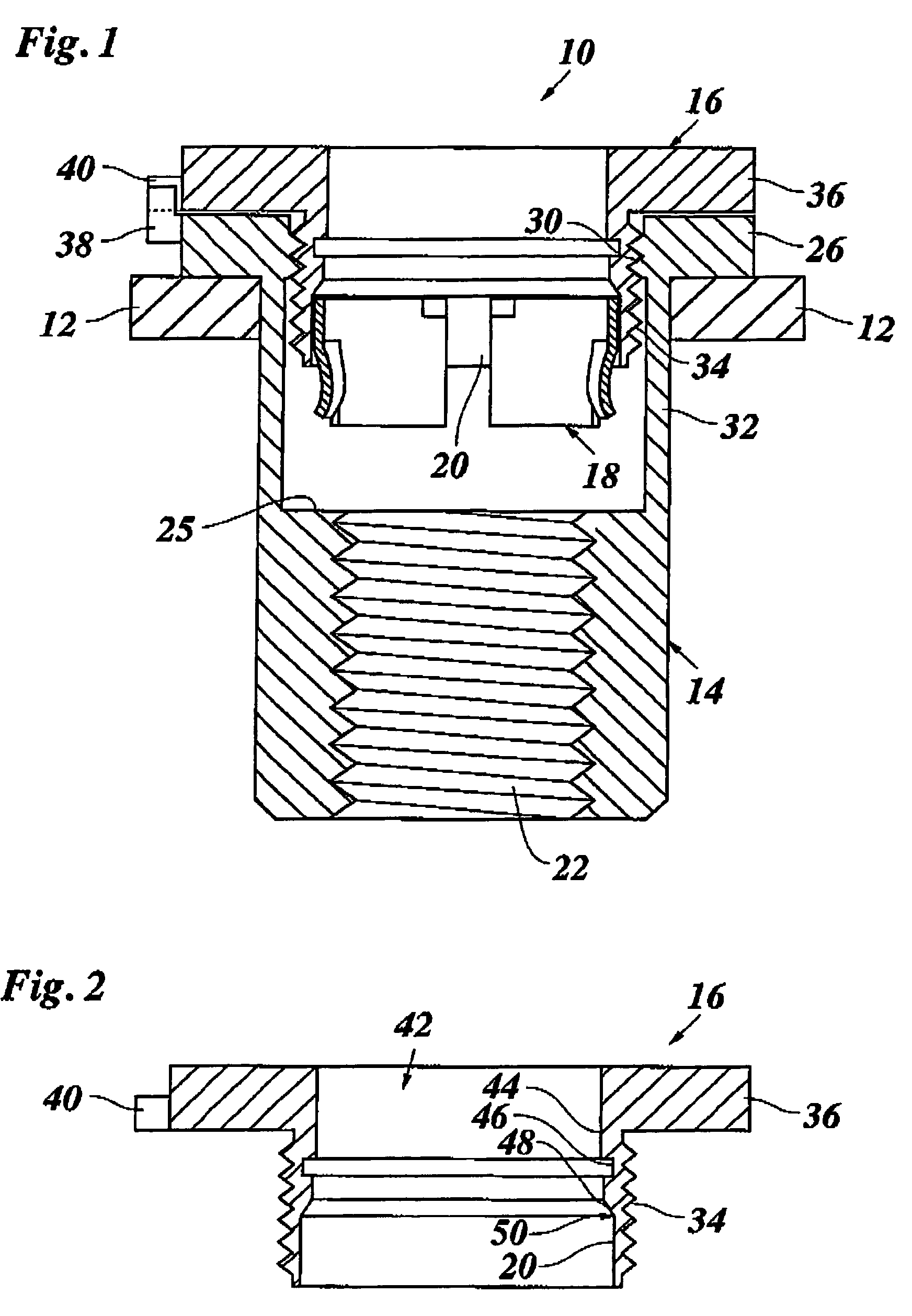
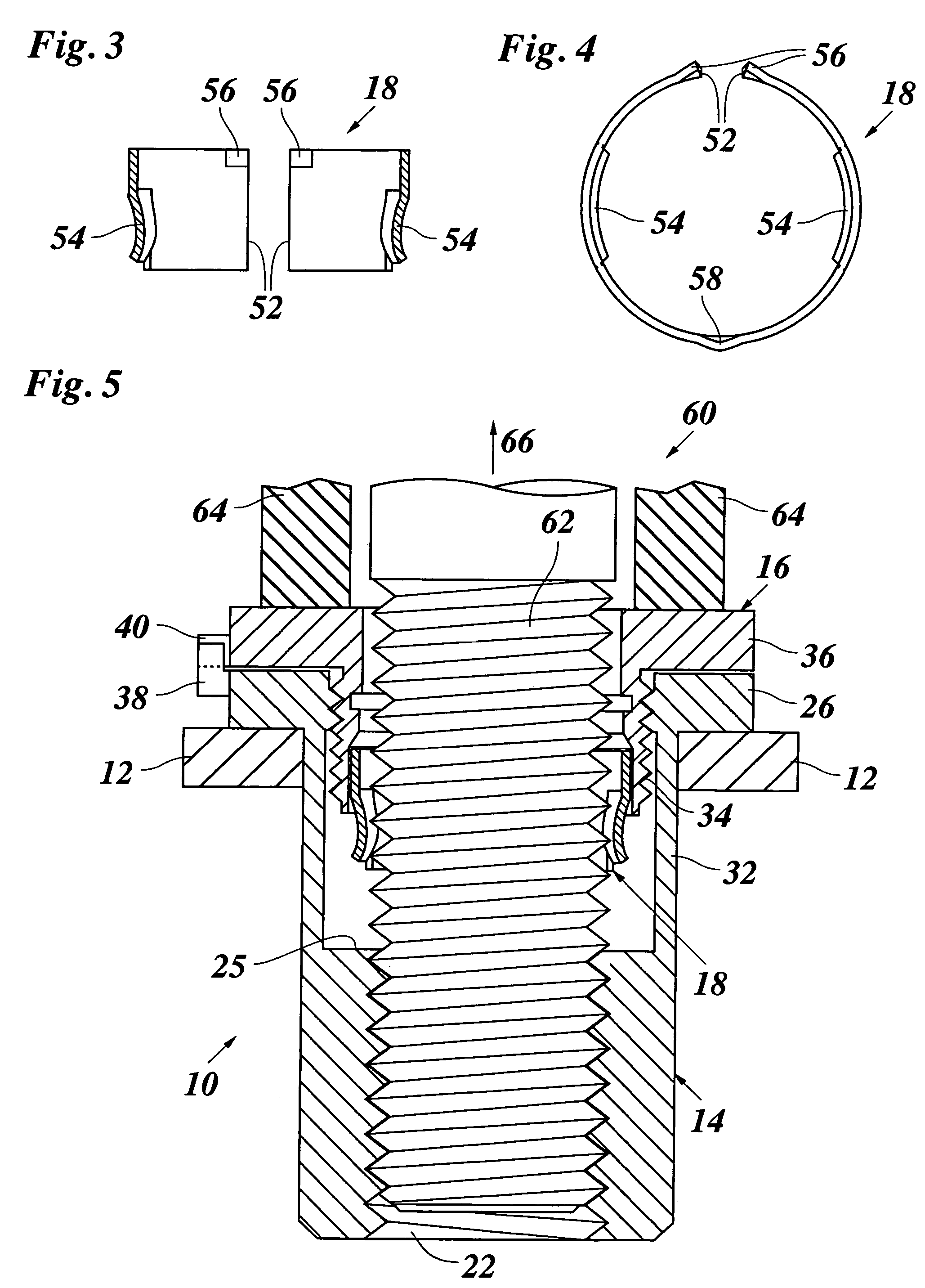
[0032]FIG. 1 shows a connecting device 10 in a supply condition, inserted in a first component part 12. The connecting device 10 is formed by a blind rivet nut 14 held at the component part 12, a spacer 16 screwed into the blind rivet nut 14, and an intermediate member in the form of an elastic ring 18 that has been inserted in a receptacle 20 on the bottom side of the spacer 16.

[0033]The blind rivet nut 14 has in its lower part a right-handed thread 22 for a connecting screw 24 (FIG. 8) the thread being surrounded at its top end by an annular support surface 25 for the elastic ring 18. At the top end, the blind rivet nut 14 engages an outer surface of the component part 12 with a flange 26. A left-handed thread 30 is formed in the top part of the blind rivet nut 14. Below the left-handed thread 30 and the flange 26, a thinner wall 32 forms a deformation portion the function of which will be explained below in conjunction with FIG. 6.

[0034]The spacer 16, which has been shown more cl...


PUM


Abstract

A device for connecting component parts includes a blind rivet nut adapted to be anchored in one component part by a riveter which has a threaded stud; a spacer which is in threaded engagement with the blind rivet nut and, by being screwed-out, reaches a position in which it is supported at the other component part; a connecting screw adapted to be screwed into the blind rivet nut; and a torque transmitting intermediate member, which is accommodated in a receptacle of the spacer and transmits a torque onto the spacer when the connecting screw is screwed in. For anchoring the blind rivet nut in the one component part, the threaded stud is capable of being inserted into the intermediate member and the spacer and then being screwed into the blind rivet nut without causing the spacer to be rotated in its screw-out direction.

Description

BACKGROUND OF THE INVENTION[0001]The invention relates to a device for connecting component parts, comprising: a blind rivet nut adapted to be anchored in one of the components parts by means of a riveter having a threaded stud; a spacer held in threaded engagement with said blind rivet nut, said spacer being brought into a support position at the other-of said component parts by being screwed out of said blind rivet nut; a connecting screw adapted to be screwed into said blind rivet nut, and a torque-transmitting intermediate member that is accommodated in a receptacle of said spacer and transmits a torque onto the spacer when the connecting screw is screwed-in.[0002]Devices of this type are known, which serve for connecting two component parts with a certain spacing relative to one another by means of a connecting screw, without the component parts being drawn together when the connecting screw is tightened. Conventionally, for establishing the connection, the blind rivet nut is a...

Claims


Application Information

Patent Timeline
IPC IPC(8): F16B43/02F16B13/04F16B5/02F16B37/06
CPCF16B5/0233F16B37/06Y10T403/7067
Inventor SCHWARZBICH, JORG
Owner BOLLHOFF VERBINDUNGSTECHNIK GMBH
Learn More