Co-prime division prescaler and frequency synthesizer

a pre-synthesizer and co-prime division technology, applied in the direction of oscillator generators, pulse automatic control, pulse technique, etc., can solve the problems of increasing the phase noise level inside the closed loop bandwidth and slowing down the settling tim

Inactive Publication Date: 2004-02-26
DSP GROUP
View PDF2 Cites 24 Cited by
  • Summary
  • Abstract
  • Description
  • Claims
  • Application Information

AI Technical Summary

Problems solved by technology

In order to change the VCO's frequency by small steps, the integer-N implementation is forced to make the phase detection frequency, F.sub.CR, equal to the step size divided by U, the resolution in changing the value of N. For closely spaced channels (small fre...

Method used


Image

  • Co-prime division prescaler and frequency synthesizer
  • Co-prime division prescaler and frequency synthesizer
  • Co-prime division prescaler and frequency synthesizer

Examples


Embodiment Construction

[0036] Various embodiments of systems and methods for performing co-prime frequency division may be implemented within frequency dividers by using T uniformly spaced phases of a clock signal to generate T cycles at the divider output during S cycles at the divider input, where S and T are co-prime and S>T.

[0037] Two integers S and T are co-prime if and only if the greatest common divisor between them is one (1). Since there are no common factors between S and T, dividing S by T results in a rational number in the form of an irreducible fraction (i.e., a fraction in its lowest terms). Note that integer division is a special case of co-prime division with T=1. Other than the degenerate case where T=1, all other choices of T will result in the irreducible fraction S / T being expressable in decimal form with a non-zero fractional component. For example, the simplest, non-degenerate co-prime frequency divider is a {{fraction (3 / 2)}} divider (S=3 & T=2) that uses 2 uniformly spaced clo...


PUM


Abstract

A system may include a control unit and a dual modulus prescaler. The control unit may generate a modulus control signal. The dual modulus prescaler may be configured to divide the frequency of an input signal by Q when the modulus control signal has a first value and to divide the frequency of the input signal by (Q+V) when the modulus control signal has a second value. Q is an irreducible fraction. The sum (Q+V) may be an integer or a fraction. The dual-modulus prescaler includes several clocked storage units (e.g., flip-flops) that are each clocked by a respective one of several equally spaced phases of the input signal. Each clocked storage unit operates in a toggle mode.

Description

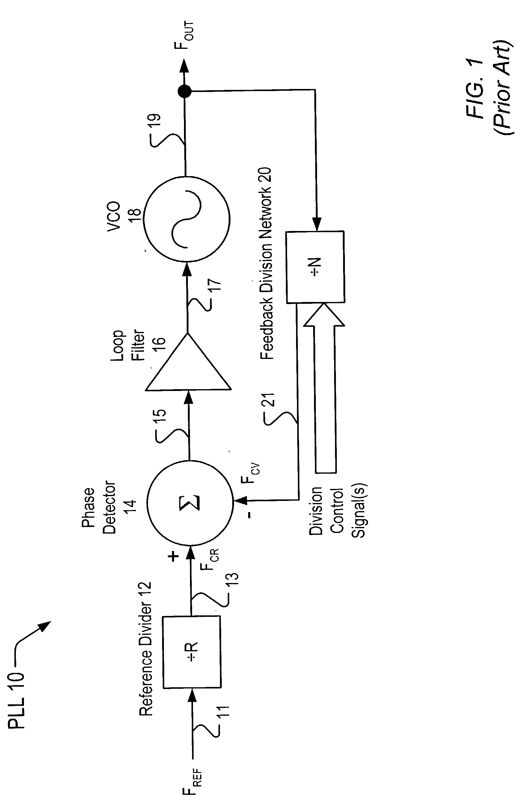
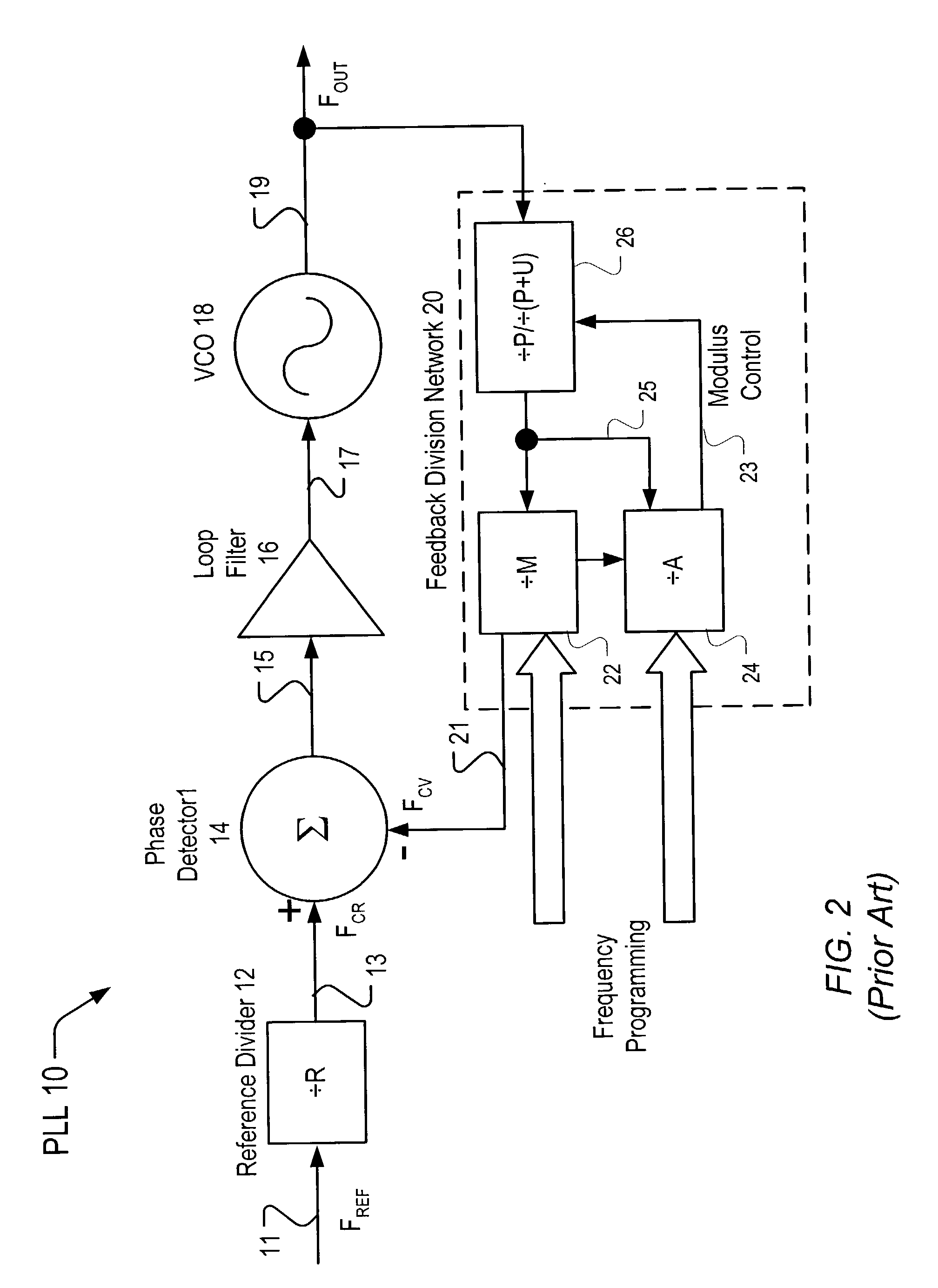
[0001] 1. Field of the Invention[0002] This invention relates to frequency dividers and dual-modulus prescalers.[0003] 2. Description of the Related Art[0004] Indirect phase-locked frequency synthesizers, commonly known as phase-locked loops (PLLs), are often used to generate a signal at a desired frequency. A block diagram of a typical PLL 10 is shown in FIG. 1. The illustrated PLL 10 includes a voltage-controlled oscillator (VCO) 18, a feedback division network 20, a reference divider 12, a phase detector 14, and a loop filter 16.[0005] The output signal 19 of the VCO 18 is divided within the feedback division network 20. The reference signal 11, typically generated by a crystal oscillator, is divided within the reference divider 12. The output 21 of the feedback division network 20 and the output 13 of the reference divider 12 are then compared within the phase detector 14. Any phase difference between the two signals results in the phase detector 14 generating a corresponding er...

Claims


Application Information

Patent Timeline
IPC IPC(8): H03K23/66H03L7/193H03L7/197
CPCH03K23/667H03L7/1974H03L7/193
Inventor GIBBONS, SCOTT G.
Owner DSP GROUP
Why Eureka
Try Eureka