
Device to alternately supply a fluid to an analyzer

Inactive Publication Date: 2004-01-08
GE ANALYTICAL INSTR
View PDF22 Cites 11 Cited by
  • Summary
  • Abstract
  • Description
  • Claims
  • Application Information

AI Technical Summary

Benefits of technology

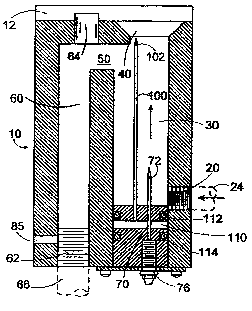
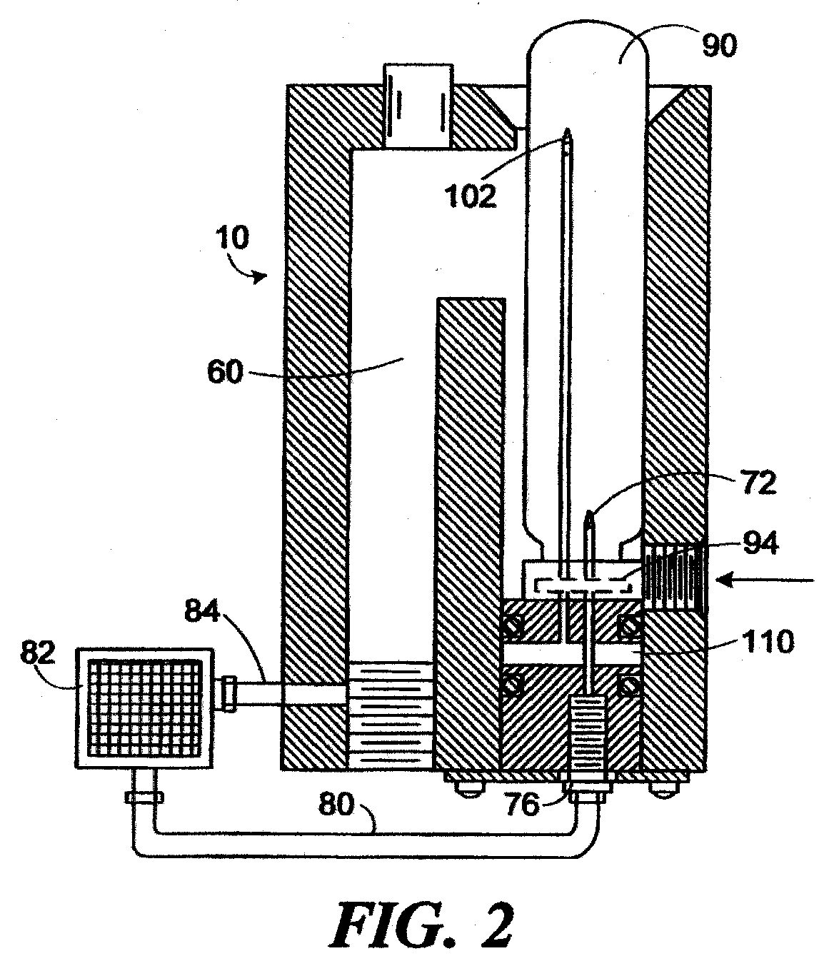
[0011] The present invention is a device and method that allows a portion of a stream of fluid to be diverted to an analyzer an also allows for a known fluid sample to be supplied to the analyzer so that the analyzer may be properly calibrated. In general, only a small portion of a fluid stream need be supplied to an analyzer; the remainder of the fluid stream may bypass the analyzer. After a potion h lid stream has been analyzed, it may be rejoined with the primary fluid flow path. Since a portion of the fluid stream is continuously diverted to the analyzer, the analyzer may continuously monitor the composition of the fluid flow instead of relying on intermittent samples.
[0012] The analyzer may receive a known fluid sample instead of a portion o the fluid stream when desired by a user. A vial or other container of the known sample may be placed in fluid commination with the analyzer, temporarily replacing the fluid stream. This may be done without disturbing the communication path between the analyzer and the fluid flow path, although the actual flow of the fluid stream is preferably halted. The known sample occupies the portion of the fluid flow path from which fluid is diverted to the analyzer so that the known sample, instead of fluid from the fluid stream, is then supplied to the analyzer. After the analyzer is tested and, if necessary, calibrated using the known sample, the container of known fluid sample may be removed, an the flow of the fluid stream may be resumed. Thus, the fluid stream an the known sample may be alternately supplied to the analyzer, without changing the connections leading to the analyzer or the fluid path. Also, the known sample may be supplied to the analyzer in a controlled condition, as the container of fluid may remain hermetically sealed until it is coupled with the analyzer. The known sample can be introduced for calibration of the device, and then removed for use of the device with a sample stream, without the use of any special tools and without any changes in the general plumbing of the system. There are no moving parts in the apparatus, an no valving or tubing sections which are unique to the known sample or to the fluid stream which can become contaminated to distort the analysis.
[0013] Preferred embodiments of the invention includes several additional features. An overflow port allows fluid to escape from the device if the fluid pressure exceeds a threshold level, thereby reducing the fluid pressure and possibly preventing damage to the device or to downstream applications. The invention may supply air to the container containing the known fluid sample as fluid drains from the container to the analyzer, so that a vacuum is prevented from forming in the container. The invention may be formed in a compact, integral unit, that allows for easy installation into a fluid flow path and that may be safely used with a wide range of fluids, even many corrosive fluids, over a wide temperature range.

Problems solved by technology

However, the composition of the fluid stream may vary considerably between the sampling intervals, so that the samples may not accurately reflect the composition of the stream.
Collecting samples from the stream is also physically complicated.
Diverting a small fraction of a fluid stream to an analyzer without using extensive and complicated plumbing can be a considerable design challenge.
Of course, if the known sample does not in fact contain the precise composition that it is belied to contain, the analyzer will be incorrectly tested and calibrated.
This is especially an issue in the pharmaceutical industry where regulations require the measurement of total organic carbon in waters for injection and purified waters at levels below 500 ppb.
Standards with such low concentrations are difficult to produce without special laboratory equipment that isolates the standard from carbon that may be in the air, and the containers for such standards must be cleaned with special cleaning agents and rinse water with ultra-low carbon concentrations.
Supplying the known sample to the analyzer may complicate the process of analyzing the fluid stream.
As well as requiring much time from the operating personnel, the process causes substantial down time to the flow of the fluid stream, which may interfere with the manufacturing, disposal or other operations involving the fluid stream.
The connecting and disconnecting process causes substantial wear on the involved parts, and hence reduces their reliability and operating life.
A mistake in this process may allow fluid to leak from the fluid stream or the analyzer, perhaps endangering the health of persons exposed to the leaked fluid and certainly disrupting whatever downstream applications are in use.
The use of valving or tubing sections that are unique to either the known sample or to the fluid stream adds complexity and moving parts, and invites contamination that can produce inaccurate or imprecise results.
In the case of the fluid stream, this contamination can lead to the disruption of the downstream application of the fluid stream, potentially fouling manufacturing or treatment equipment.
In the case of the known sample, contamination will result in an inaccurate sample being supplied to the analyzer, resulting in the analyzer being improperly tested and calibrated.
When the fluid stream is once again connected to the analyzer, it may be erroneously analyzed by the improperly calibrated analyzer.
The above complications may prevent fluid stream operators from testing and calibrating an analyzer as often as may be optimally desired, or even to entirely forego testing and calibrating the analyzer on any sort of a regular basis whatsoever.
A major drawback to that approach, however, is that many samples are not stable over time; therefore, the sample being used for calibration could have deteriorated at the time of the calibration in a manner that produces an erroneous calibration.
Further, many samples used for calibration cannot be stored indefinitely within the apparatus due to safety concerns or, especially with respect to low level samples, contamination concerns.
In consumer products, trace levels of sulfur-containing compounds can impart an objectionable taste and odor.
In petrochemical applications, trace sulfur contaminants can poison catalysts, damaging or destroying processing equipment.

Method used


Image

  • Device to alternately supply a fluid to an analyzer
  • Device to alternately supply a fluid to an analyzer
  • Device to alternately supply a fluid to an analyzer

Examples


Embodiment Construction

Cross Reference to Related Applications

[0001] This application is a continuation of U.S. application Serial No. 09 / 894,313, filed June 27, 2001, now pending, which in turn was a continuation of U.S. application Serial No. 09 / 368,990, filed August 5, 1999, which became U.S. Patent No. 6,271,043 issued August 7, 2001, which in turn was a division of U.S. application Serial No. 09 / 191,610, filed November 13, 1998, which became U.S. Patent No. 5,976,468, issued November 2, 1999, which in turn was a continuation of U.S. application Serial No. 08 / 629,609, filed April 9, 1996, which became U.S. Patent No. 5,837,203, issued November 17, 1998.

Background of Invention

[0002] The present invention relates to the field of chemical analysis, and more particularly to a method and a device that supplies a portion of fluid from a stream to a chemical analyzer and, when desired, supplies fluid of known chemical composition to the analyzer.

[0003] Fluid analysis is used in a wide variety of research, ma...


PUM


Abstract

Abstract of the Disclosure Apparatus and methods for supplying a portion of a fluid stream and, alternately, a fluid of known composition and concentration to an analyzer are provided. The fluid stream is directed through a series of connected chambers formed in an integral housing. A sampling needle has an inlet in one of the chambers and an outlet in fluid communication with the analyzer. When desired, a tube or vial containing a known fluid may be inserted into a chamber containing the sampling needle, so that the known fluid will be supplied to the analyzer. A second needle provides ventilation to the vial to prevent the formation of a vacuum as the known fluid is drained from the vial.

Description

Detailed Description of the InventionCross Reference to Related Applications[0001] This application is a continuation of U.S. application Serial No. 09 / 894,313, filed June 27, 2001, now pending, which in turn was a continuation of U.S. application Serial No. 09 / 368,990, filed August 5, 1999, which became U.S. Patent No. 6,271,043 issued August 7, 2001, which in turn was a division of U.S. application Serial No. 09 / 191,610, filed November 13, 1998, which became U.S. Patent No. 5,976,468, issued November 2, 1999, which in turn was a continuation of U.S. application Serial No. 08 / 629,609, filed April 9, 1996, which became U.S. Patent No. 5,837,203, issued November 17, 1998.Background of Invention[0002] The present invention relates to the field of chemical analysis, and more particularly to a method and a device that supplies a portion of fluid from a stream to a chemical analyzer and, when desired, supplies fluid of known chemical composition to the analyzer.[0003] Fluid analysis is u...

Claims


Application Information

Patent Timeline
IPC IPC(8): G01N1/00
CPCG01N35/1079G01N2001/2893Y10T436/10Y10T436/11Y10T436/117497Y10T436/235Y10T436/2575Y10T436/25
Inventor GODEC, RICHARD D.SILVESTER, FRANK J.BATEMAN, BLAINE R.
Owner GE ANALYTICAL INSTR
Learn More