
Cartridge with connection for a pump-drive and fluid handling system

a technology of fluid handling system and cartridge, which is applied in the direction of liquid transfer device, laboratory glassware, instruments, etc., can solve the problems of entail large financial and handling-technical expenditure, impose particularly high demands on the cleanliness of the procedural apparatus, and have a large number of handling events, etc., and achieve sufficient economic feasibility and minimal handling effort

Inactive Publication Date: 2007-02-27
DIRECTIF +1
View PDF28 Cites 3 Cited by
  • Summary
  • Abstract
  • Description
  • Claims
  • Application Information

AI Technical Summary

Benefits of technology

[0010]An object of the present invention is to enable the handling of a fluid in cartridges with only a minimal handling effort, but which is sufficiently economically feasible for single (one-time) use products.
[0012]The invention is based on the use of a cartridge that possesses an integral pump system actuated from outside the cartridge to handle fluids. As used herein, the term cartridge means a substance container, adapted to particular requirements, that can have thick or thin walls and may have additional features such as integrated heating or cooling systems or the like. The pump system, for example a pump piston, can automatically couple and decouple with the pump actuation of a handling system by means of a positive-fit connection. It is thus not necessary to use additional pump systems such as, for example, injectors or piston pumps for handling. In the handling, additional effort for the coupling and decoupling of the cartridge to the handling system thus can be avoided.
[0013]In the invention the pump system, in addition to the cartridge, is also manufacturable from inexpensive components such as molded plastic components. The cartridge thus can be manufactured at a low cost and made available in large quantities. The ability to economically manufacture large quantities is of particular advantage in the use of the cartridge for central, serial laboratory examination of large numbers of probes that must be spatially separately removed on site. The low-cost manufacturability of the cartridges in large numbers makes them economically useable in addition as a one-time product. Additionally, the logistic effort for frequent, spatially separate use can thereby be reduced. Time and expense for the complex cleaning of the cartridges is not needed with regard to analysis methods that have particular requirements as to purity. In spite of this, the cartridges not yet contaminated in the manufacture are sterilized or cleaned according to requirements and subsequently packed sealed, for example in a blister pack, as is typical for medical products. The substantially complicated cleaning of already used, thus contaminated cartridges can then be completely dispensed with.
[0014]In an embodiment of the invention, the production outlay is minimized by designing the automatically producible connection between integral pump system of the cartridge and the pump actuator of the analysis device or dosing device without complicated, fine mechanical working parts, and solely on the basis of an elastic, formed component. The elastic, formed component is fashioned such that has catches or jaw elements that, upon infeed of the integral pump system via the external pump actuator, enters into a positive-fit connection by means of a longitudinal motion. The positive-fit connection allows the integral pump system also to be retracted by the pump actuator, with the positive-fit connection becoming detached when, upon the retraction, the integral pump system once again reaches its starting point.
[0015]A further advantage is that the integrated pump system is implemented as a one-time use system. It can, if necessary, undergo the same cleaning steps as the entire cartridge, and therefore fulfills the same requirements for purity. In the one-time use, it must likewise not be elaborately cleaned for reuse. Moreover, the purity of the fluids to be handled also benefits from the integration of the pump system, because the transfer via and the contact with additional pump systems, for example injectors, is avoided.
[0016]A further object of the invention is to provide a system that enables the handling of fluids by means of a low-cost producible cartridge that can be automatically coupled and again decoupled with the system via a positive-fit connection. Due to the automatic coupling, the number of individual handling steps is reduced. The low-cost manufacturability of the cartridges enables the economic application in large quantities and use as a one-time product.

Problems solved by technology

Since genetic contamination is also thereby multiplied, this method poses particularly high demands on the cleanliness of the procedural apparatuses.
In particular in large industrial application measures, immense numbers of handling events can ensue for individual liquid or gas quantities.
While the handling of fluids under everyday conditions poses no particular problem, high numbers of handling events or high requirements of a particular degree of purity entail substantially large financial and handling-technical expenditure.
The need for extreme cleanliness of the receptacles requires a number of individual cleaning steps with correspondingly high labor expenditure.
If high requirements as to purity and handling coincide with high handling high numbers of units, the one-time use of the equipment has heretofore been uneconomical, and in addition the need for a large personnel staff is inevitable, due to the high price of the complex devices for handling and for cleaning.
Even when it is only large numbers of handling events that occur, a significant handling burden already exists that cannot be maintained.
A disadvantage, however, is that the cartridges must be individually handled in similarly large numbers, and devices provided for this use must be installed.

Method used


Image

  • Cartridge with connection for a pump-drive and fluid handling system
  • Cartridge with connection for a pump-drive and fluid handling system
  • Cartridge with connection for a pump-drive and fluid handling system

Examples


Embodiment Construction

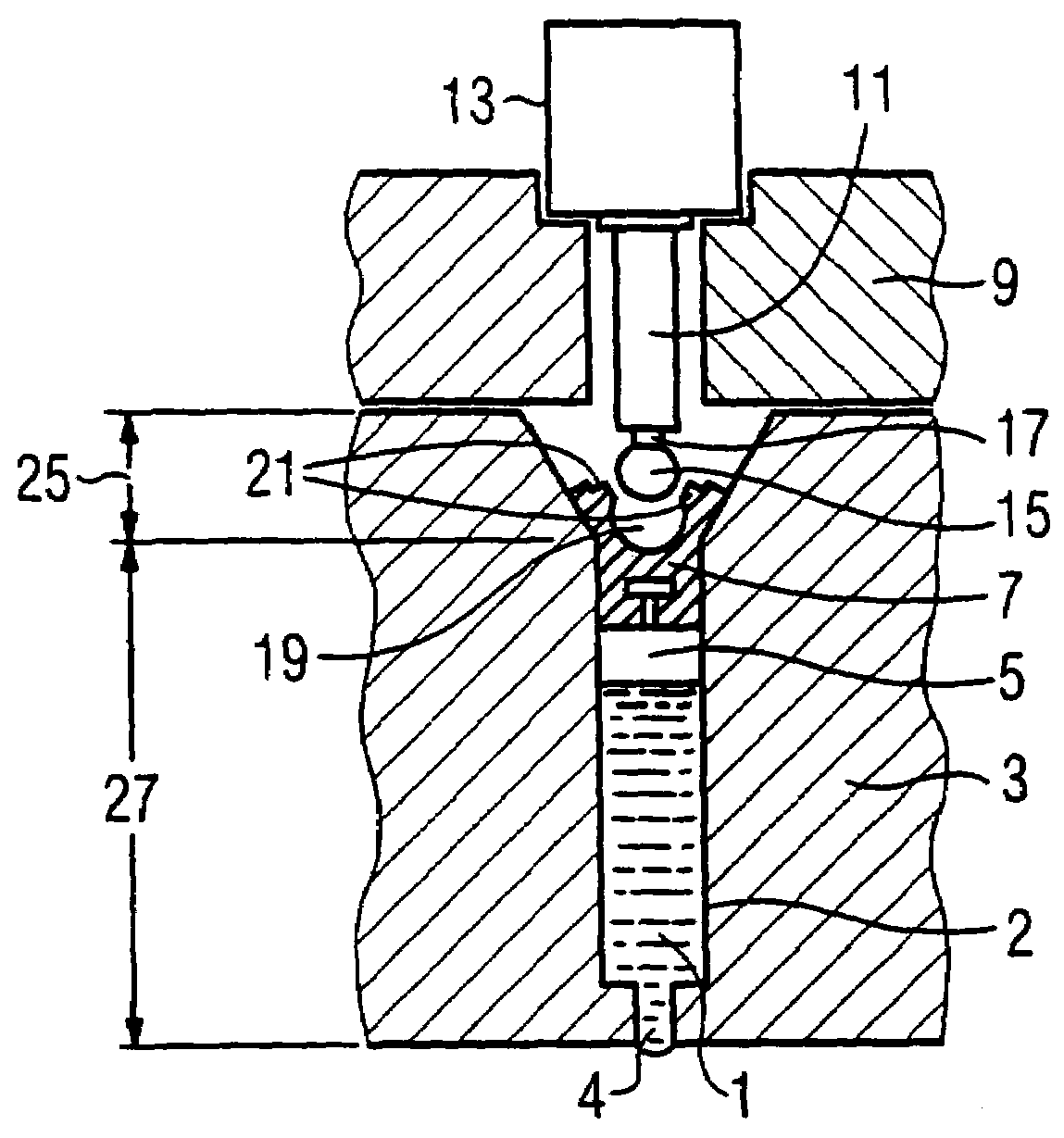
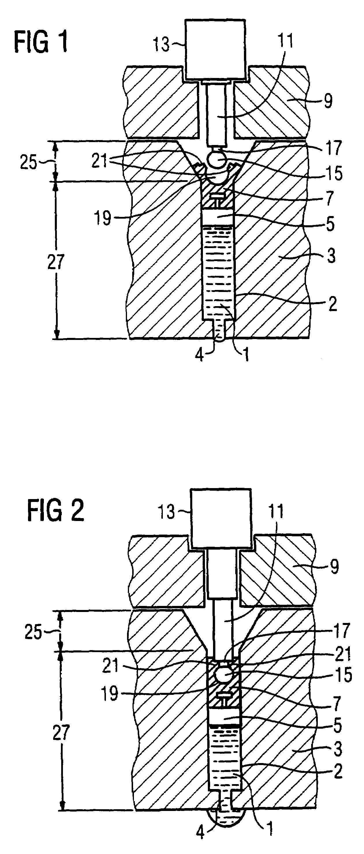
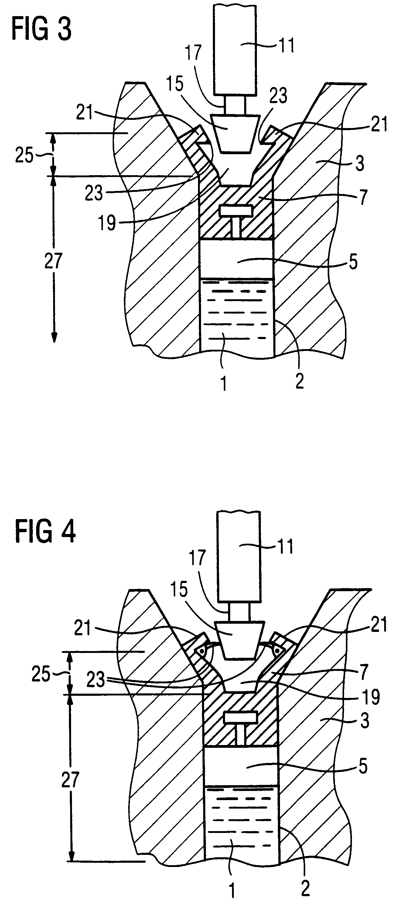
[0021]FIG. 1 shows a system according to the invention with a cartridge 3 and a dosing device or analysis device 9. The cartridge 3 can be formed of plastic, metal or another suitable material, dependent on the liquid or the gas to be handled. The cartridge 3 has a tank 2 shaped as a cylinder, the cross-section of which can be arbitrarily fashioned, but the simpler shapes are semi-circular and circular. Located in the tank 2 in FIG. 1 is a fluid 1 that is pumped in via an opening 4 lying the front wall of the tank 2. A piston 5 is arranged in the tank 2 that can be moved forward and back in order to pump the fluid in or out. So that the pump 5 can form a sealed connection with the inner wall of the tank 2, the surfaces on both sides have a suitable surface finish. Moreover, at least one of the two sealing components can be made of elastic material. To satisfy the requirement for impermeability, if needed, seal rings can be arranged on the piston 5 (which are not shown in FIG. 1).

[00...


PUM


Abstract

In a cartridge for a fluid, as well as a system for handling a fluid using such a cartridge, the cartridge has a tank shaped as a cylinder with an opening to admit and discharge the fluid, as well as a piston that can be moved forward and / or back in the tank in order to pump the fluid in or out through the opening. The piston has a connection element that can be connected with an actuator in order to move the piston forward and / or back. The connection element and the actuator are adapted to one another such that the connection is automatically closed in a first longitudinal section of the tank, given movement of the piston in the longitudinal direction and is automatically released again given movement in the opposite direction, and the connection remains closed in a second longitudinal section of the tank given movement of the piston into this second longitudinal section.

Description

BACKGROUND OF THE INVENTION[0001]1. Field of the Invention[0002]The present invention concerns a cartridge for handling and transport of a fluid (liquid or gaseous substance), as well as a system for handling a fluid using such a cartridge. The invention concerns in particular a cartridge for handling a medical fluid as well as an analysis device to examine medically relevant properties of a fluid using such a cartridge.[0003]2. Description of the Prior Art[0004]In medical diagnostics, a number of examinations are implemented on liquids or gases (fluids), for example blood, urine, saliva, gastric juices, or respiratory air. The examinations can provide the analysis of widely varied parameters of chemical, microbiological, or physical properties. In addition to the ascertainment of measurements such as the pH value, the content of particular chemical elements or compounds, or the determination of the bacteria count, microbiological analysis methods play an increasingly larger role. T...

Claims


Application Information

Patent Timeline
IPC IPC(8): B67D5/42B67D7/60B01L3/02G01N1/14
CPCB01L3/0217G01N1/14B01L2200/02B01L2200/141B01L2200/16B01L2200/04
Inventor KRUEGER, ANDREAS
Owner DIRECTIF
Learn More