
Method and apparatus for dispensing liquids as an atomized spray

a technology of liquid spray and atomization, which is applied in the direction of recording apparatus, instruments, single-unit apparatus, etc., can solve the problems of liquid undetected outflow from the opening, problems arise, and inability to eject atomized fluid droplets

Inactive Publication Date: 2004-01-01
STAMFORD DEVICES LTD +1
View PDF2 Cites 61 Cited by
  • Summary
  • Abstract
  • Description
  • Claims
  • Application Information

AI Technical Summary

Benefits of technology

The device effectively ejects fluid droplets over a wide range of pressures, enhancing transfer efficiency and reducing environmental impact by eliminating the need for propellants, while maintaining precise control over fluid delivery.

Problems solved by technology

The first type is not capable of ejecting atomized fluid droplets.
When volatile fluids are used, problems arise.
Hence, liquid may undesirably outflow from the opening.
The discharge opening will clog, restricting or stopping further discharge.
These problems are prevalent with volatile fluids such as fuel, paint, or other coating materials.
The use of air as a propellant in paint spray application causes overspray, in that part of the paint droplets escape to the atmosphere and cause air pollution.
The use of propellants in conventional aerosols, commonly known as volatile organic chemicals (VOCs), has a negative effect on the environment and on human health.
If the fluid supply exceeds the maximum ejection rate of the apertures, excessive fluid may overflow from the supply side of the oscillating surface.
When the fluid used is paint or ink, overflow is undesirable.

Method used


Image

  • Method and apparatus for dispensing liquids as an atomized spray
  • Method and apparatus for dispensing liquids as an atomized spray
  • Method and apparatus for dispensing liquids as an atomized spray

Examples


Embodiment Construction

[0062] Referring now to FIG. 1, it will be seen that the fluid ejection device 10 of the present invention comprises a vibrating surface 12 having a perimeter area 14 and a center area 16. The perimeter 14 of vibrating surface 12 is affixed to an oscillator 18 which may, for example, be piezoceramic. The center area 16 of vibrating surface 12 is provided with a planar surface 15 through which there are apertures 22. The portion of center 15 having the apertures is in surface tension contact with a fluid film 19 at the back side of planar surface 15 to produce an ejection of fluid droplets 20.

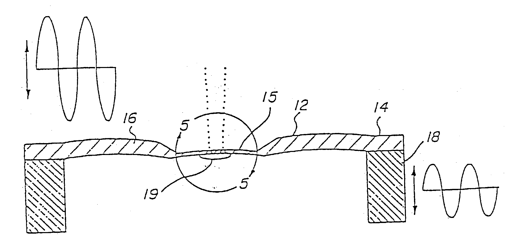
[0063] The oscillatory motion of the vibrating surface 12 is shown in FIG. 2. It will be seen therein that the perimeter 14 of the vibrating surface 12, by virtue of its contact with the oscillator 18, oscillates in a vertical direction, as viewed in FIG. 2, with an oscillating characteristic shown in the graph at the rightmost portion of FIG. 2. As also seen in FIG. 2, the center 16 of vibratin...


PUM


Abstract

The invention provides exemplary methods and apparatus for dispensing liquids as an atomized spray. In one particularly preferably method, a liquid is dispensed as an atomized spray from a vibratable member having a front surface and a rear surface, with the member having at least one tapered hole between the surfaces for dispensing the liquid. The tapered hole has a larger cross-sectional area at the rear surface than at the front surface. The liquid is delivered from a supply container to the rear surface of the vibratable member in an amount sufficient to cover the hole with liquid. The vibratable member is then vibrated to dispense at least a portion of the liquid through the hole and from the front surface. Additional liquid is delivered from the supply container and to the rear surface in volumes that are substantially equal to the volumes dispensed.

Description

[0001] This application is a continuation-in-part application of U.S. patent application Ser. No. 08 / 163,850, filed on Dec. 7, 1993, which is a continuation-in-part of U.S. patent application Ser. No. 07 / 726,777, filed on Jul. 8, 1991 (now abandoned), which is a continuation-in-part of U.S. patent application Ser. No. 07 / 691,584, filed on Apr. 24, 1991, now U.S. Pat. No. 5,164,740. The complete disclosures of all these applications are herein incorporated by reference.[0002] 1. Field of the Invention[0003] The present invention relates to the fields of liquid spray and atomization of liquids of all kinds and, more specifically, finds utility in humidification and misting, industrial cleaning, surface coating and treatment, particle coating and encapsulating, fuel atomization, deodorization, disbursement of insecticides, aerosols, and medical spray applications.[0004] 2. Description of Related Art[0005] Many types of ultrasonic fluid ejection devices have been developed for atomizing...

Claims


Application Information

Patent Timeline
Patent Type & Authority Applications(United States)
IPC IPC(8): A61M11/00A61M15/00A61M16/00B05B11/02B05B12/08B05B17/00B05B17/06B41J2/025B41J2/04G01D15/16
CPCA61M11/005B41J2202/15A61M15/0085A61M2016/0039A61M2205/3306A61M2205/3379A61M2205/3382A61M2205/3386A61M2205/3389A61M2205/8206B05B12/08B05B17/0646B05B17/0676B05B17/0684B41J2/025B41J2/04A61M15/0065A61M11/006A61M15/025A61M15/0081
Inventor IVRI, YEHUDA
Owner STAMFORD DEVICES LTD
Learn More