
Method for subdividing multilayer optical film cleanly and rapidly

a multi-layer optical film and sub-divide technology, applied in the direction of instruments, manufacturing tools, synthetic resin layered products, etc., can solve the problems of large number of film pieces, large thickness of sub-strate, and limited size, so as to reduce the electrostatic attraction

Inactive Publication Date: 2003-11-27
3M INNOVATIVE PROPERTIES CO +1
View PDF2 Cites 10 Cited by
  • Summary
  • Abstract
  • Description
  • Claims
  • Application Information

AI Technical Summary

Benefits of technology

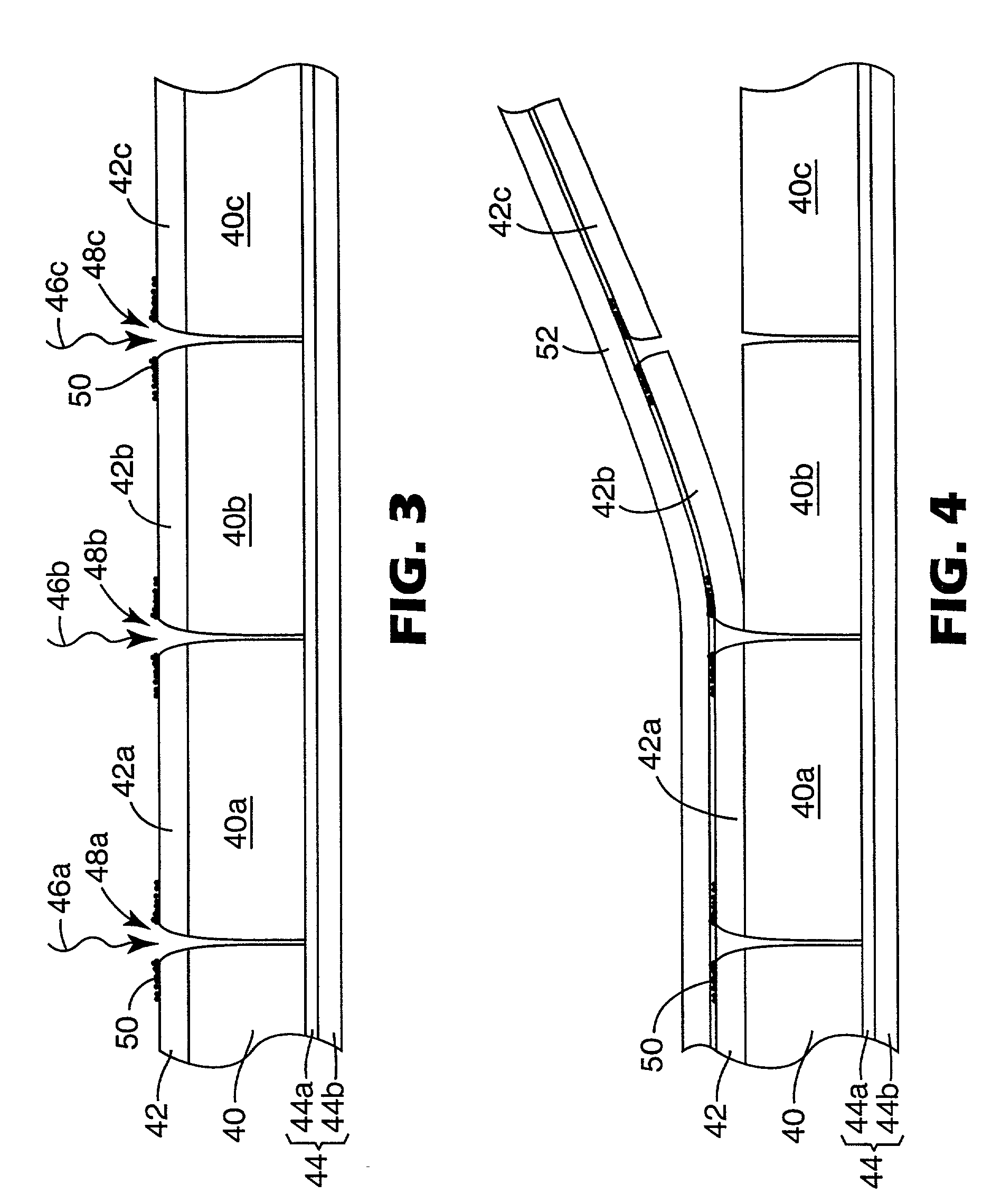
[0008] Preferably, at least the first liner is applied to the film body using electrostatics. After the cut lines are formed with the laser radiation and before removal of the pieces of the first liner from the pieces of multilayer optical film body, a neutralizer member can be used to reduce the electrostatic attraction between the first liner and the multilayer optical film body.

Problems solved by technology

Typically, the substrate is a relatively thick piece of glass, limited in size due to constraints on the vacuum chamber volume and / or the degree of uniformity possible by the deposition process.
Many product applications, however, require relatively small and numerous pieces of film.
However, the forces exerted on the film by the cutting mechanism can produce layer delamination in a region along the cut line or edge of the film.
Because the multilayer optical film relies on intimate contact of the individual layers to produce the desired reflection / transmission characteristics, the delamination region fails to provide those desired characteristics.
In others--particularly where it is important for substantially the entire piece of film from edge to edge to exhibit the desired reflection or transmission characteristics, or where the film can be subjected to mechanical stresses and / or wide temperature variations that could cause the delamination to propagate in the film over time--the delamination can be highly detrimental.

Method used


Image

  • Method for subdividing multilayer optical film cleanly and rapidly
  • Method for subdividing multilayer optical film cleanly and rapidly
  • Method for subdividing multilayer optical film cleanly and rapidly

Examples


example

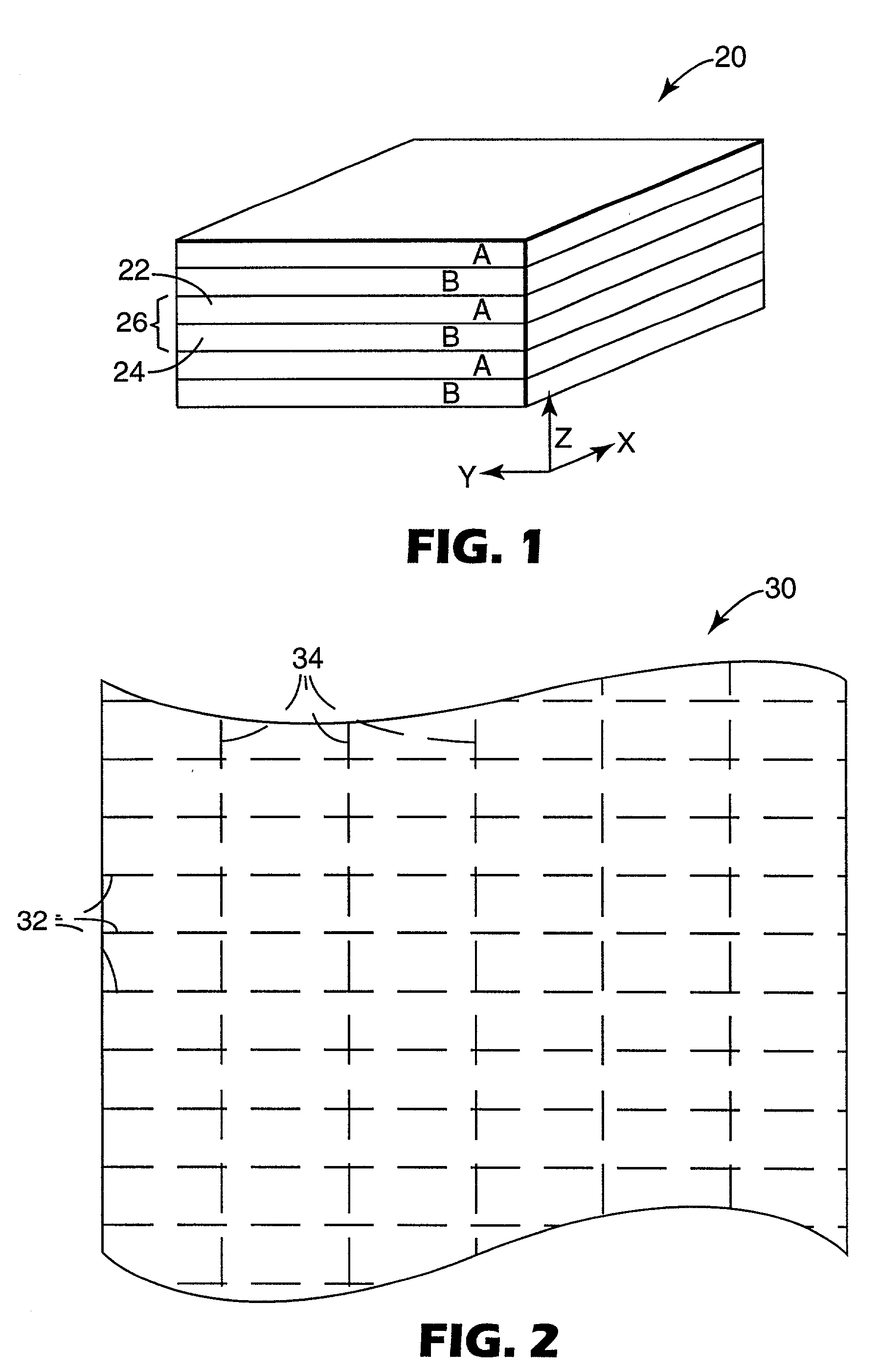
[0051] A polymeric multilayer interference film was manufactured by coextruding alternating layers of a low melt coPEN made from a 90 / 10 copolymer of polyethylene naphthalate (PEN) / polyethylene terephthalate (PET) and polymethylmethacrylate (PMMA) at about 277.degree. C. to form an extrudate having 224 individual layers sandwiched between two outer skin layers composed of the low melt coPEN. These layers defined an optical packet consisting essentially of 112 unit cells with an approximately linear thickness gradient along an axis perpendicular to the stack. The thickest unit cell, located at one side of the packet, was approximately 1.3 times thicker than the thinnest unit cell, located at the other side of the packet. The optical packet was asymmetrically multiplied to give a multilayer optical film construction having 448 individual layers with outer skin layers and an interior polymer boundary layer (PBL) between packets. The layer multiplication was carried out so that one of t...


PUM

PropertyMeasurementUnit
Flow rateaaaaaaaaaa

Abstract

Polymeric multilayer optical films, and laminate bodies that include such films, are cut or subdivided into one or more discrete pieces by removably applying a first and second liner to opposed major surfaces of the multilayer optical film. Laser radiation is then directed at the multilayer optical film through the first liner in such a way as to produce cut lines that define a plurality of pieces of the first liner and of the multilayer optical film. Thereafter, the plurality of pieces of the first liner are removed from the plurality of pieces of the multilayer optical film while the pieces of multilayer optical film are supported by the second liner. Application of the first liner to the multilayer optical film can be accomplished with electrostatics.

Description

[0001] The present invention relates to methods of cutting or subdividing an optical body comprising a multilayer optical film into a plurality of smaller pieces.[0002] Multilayer optical films, i.e., films that provide desirable transmission and / or reflection properties at least partially by an arrangement of microlayers of differing refractive index, are known. It has long been known to make such multilayer optical films by depositing a sequence of inorganic materials in optically thin layers ("microlayers") on a substrate in a vacuum chamber. Typically, the substrate is a relatively thick piece of glass, limited in size due to constraints on the vacuum chamber volume and / or the degree of uniformity possible by the deposition process.[0003] More recently, multilayer optical films have been demonstrated by coextrusion of alternating polymer layers. See, e.g., U.S. Pat. Nos. 3,610,724 (Rogers), U.S. Pat. No. 4,446,305 (Rogers et al.), U.S. Pat. No. 4,540,623 (Im et al.), U.S. Pat. N...

Claims


Application Information

Patent Timeline
IPC IPC(8): B23K26/00B23K26/08B23K26/18B23K26/38B32B27/08B32B37/26B32B38/00G02B5/28
CPCB23K26/0033B23K26/009B23K26/0039B23K26/0048B23K26/0846B23K26/18B23K26/38B23K2201/16B23K2203/16B32B27/08B32B37/025B32B37/26B32B38/0004B32B2310/0843B32B2551/00G02B5/287B23K26/0036B23K26/0006B23K2101/16B23K2103/16B23K2103/172B23K2103/40B23K2103/42B23K2103/50
Inventor TAIT, BRUCE E.WHEATLEY, JOHN A.DOBRZYNSKI, STEVEN J.MORTENSON, DAVID K.
Owner 3M INNOVATIVE PROPERTIES CO
Learn More