
Optical isolators and methods of manufacture

Inactive Publication Date: 2003-11-06
CORNING INC
View PDF29 Cites 18 Cited by
  • Summary
  • Abstract
  • Description
  • Claims
  • Application Information

AI Technical Summary

Benefits of technology

[0012] Chemical bonds can be formed between a Faraday rotator having a first bonding surface and a beam splitting element or polarizer having a second bonding surface by contacting at least one of the bonding surfaces with a solution to facilitate chemical bonding between the first and second bonding surfaces. Acidic solutions or solutions having a pH greater than 8 can be used. Hydroxide solutions such as ammonium hydroxide are examples of high pH solutions that may be used in accordance with this embodiment. Bonding may be facilitated by providing termination groups on at least one of the bonding surfaces selected from the group consisting of --OH, .ident.Si--OH, .dbd.Si--(OH).sub.2, --Si--(OH).sub.3 and --O--Si--(OH).sub.3, and combinations thereof. Bonding may further be facilitated by including lithium on at least one of the bonding surfaces.
[0013] In certain embodiments, the method may include providing an antireflective coating on at least one of the bonding surfaces, and in preferred embodiments, the coating comprises silica. In other embodiments, bonding may involve providing adsorbed hydroxyl groups on at least one of the bonding surfaces. Thereafter, the adsorbed hydroxyl groups at the interface between the bonding surfaces can be eliminated, by for example, heating the bonding surfaces to a temperature less than the Curie temperature of the Faraday rotator.
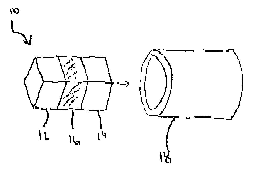
[0032] In an alternative embodiment shown in FIG. 1B, polarization independent isolator cores 20 can be manufactured by sandwiching a Faraday rotator 26 between a pair of beam splitters 22, 24. Typically, the beam splitters 22, 24 comprise a birefringent material such as single crystal rutile or yttrium vandanate in the form of a plate or wedge, but other types of beam splitters may be used in accordance with the invention. Typically, polarization independent isolators also include a half wave plate 25 disposed between Faraday rotator 26 and beam splitter 24. The adjacent surfaces that make up the isolator core are bonded together using chemical or vacuum bonding techniques as described above. As in the previously described embodiment, if non-latching materials are used to form the Faraday rotator 26, the isolator core 20 is inserted in a magnet 28. However, if latching garnet is used to form the Faraday rotator, the magnet can be eliminated.
[0033] In an alternative embodiment of the optical isolator not shown), the optical isolator can include, bonded to the exposed end of the polarizers or beam splitters, an optical lens. It is contemplated that either one or both of the polarizers or beam splitters can include a bonded lens. As in the previously described embodiment, the adjacent surfaces of the polarizer or beam splitter and the lens are bonded together using chemical or vacuum bonding techniques as described above. The function of the lens bonded to the polarizer or beam splitter is to assist in collimating the signal through the optical isolator and or assist in focusing the signal that is emitted from the optical isolator. Preferably, the type of lens that can be utilized for this application includes, but is not limited to, gradient index (GRIN) lenses.

Problems solved by technology

Back reflections result in reduced performance of the system and sometimes can adversely affect the transmission source, typically a laser.
A limitation of mechanical assembly includes the introduction of optical signal loss due to air gaps that tend to exist between the surfaces of the adjacent parts, and the need to align and package individual components after dicing to final dimensions.
However, the adhesive assembly has the disadvantage of introducing optical loss when the epoxy or adhesive is in the optical path of the isolator.
Another disadvantage of adhesive assembly is that when the isolator assembly encounters temperature variations, the epoxy or adhesive can fail due to CTE mismatches and / or temperature dependence of the adhesive's refractive index, causing delamination of the components.
An additional disadvantage of adhesive assembly is that the epoxy may be susceptible to laser damage, causing optical loss, or, in some cases, catastrophic failure of the device in high power applications.

Method used


Image

  • Optical isolators and methods of manufacture
  • Optical isolators and methods of manufacture
  • Optical isolators and methods of manufacture

Examples


example 2

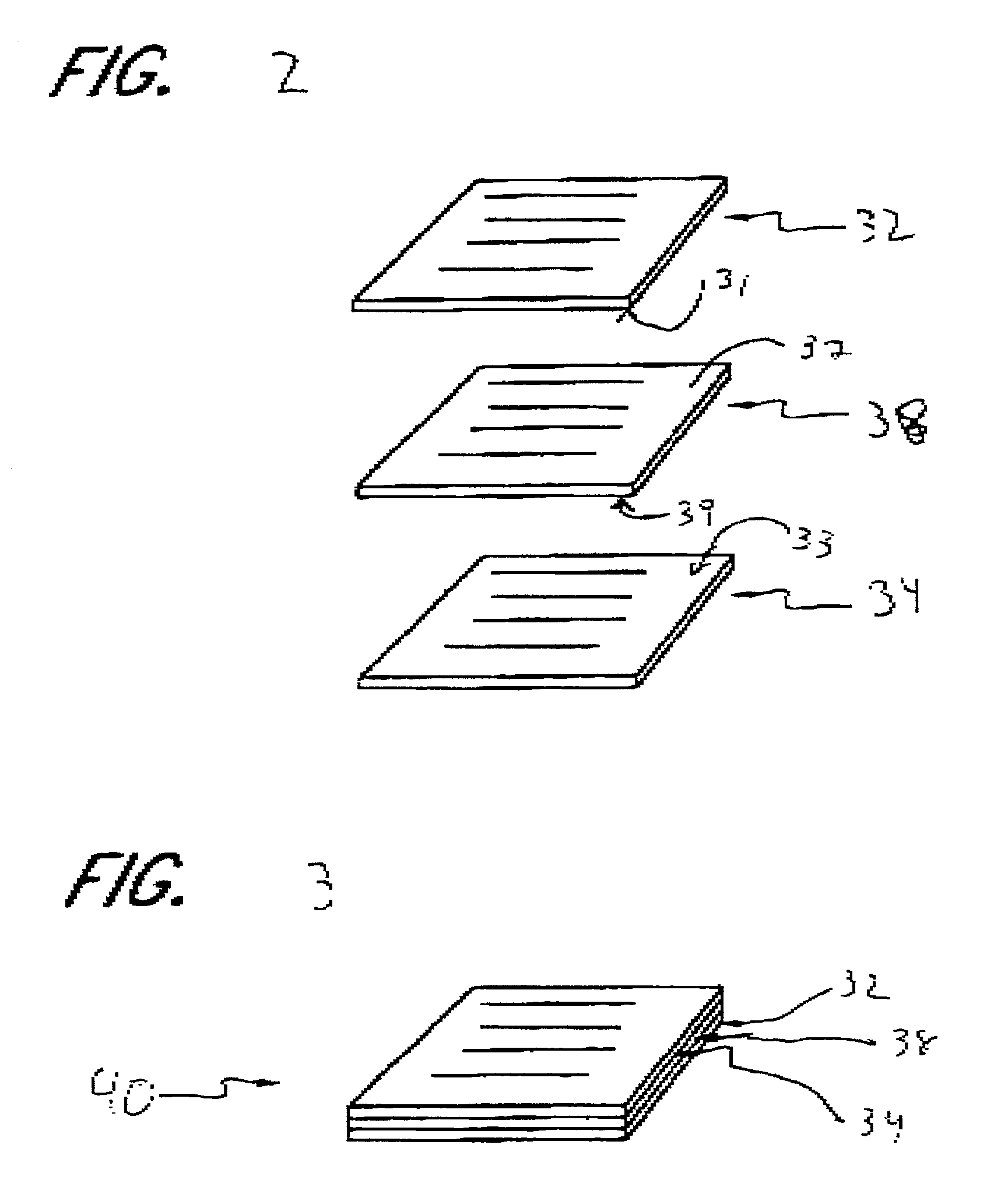
[0038] This example demonstrates that isolator cores comprising Polarcor.TM. glass sheets sandwiched together with a Faraday rotator material sheet can be bonded together and diced into isolator cores without delamination. Two Polarcor.TM. glass sheets previously polished to less than 1 micron flatness and AR coated were pretreated by coating with lithium metal by thermal evaporation under vacuum and heat treated at 200.degree. C. for 24 hours. The lithium coated Polarcor.TM. sheets along with a flat, AR-coated bismuth iron garnet (BIG, purchased from MGC) sheet were cleaned with a detergent solution (Microclean CA05), rinsed in water and soaked in 10 volume % nitric acid solution for 1 hour. The acid-soaked samples were rinsed in water and then soaked in a 15 volume % ammonium hydroxide solution for 1 hour. The samples were rinsed again, and the bonding surfaces were maintained in a wet condition, stacked so that the Polaror.TM. sheets sandwiched the Faraday rotator sheet, and bond...


PUM

PropertyMeasurementUnit
Temperatureaaaaaaaaaa
Antireflectiveaaaaaaaaaa
Covalent bondaaaaaaaaaa

Abstract

Optical isolators and methods of manufacturing optical isolators are disclosed. The optical isolators are manufactured by directly bonding the parts of the isolators without the use of adhesive or mechanical devices to hold the individual parts together.

Description

[0001] This invention relates to optical isolators and methods of manufacturing optical isolators. More particularly, the invention relates to direct bonding of the materials comprising optical isolators and methods of performing such direct bonding.[0002] Optical isolators are devices used in optical transmission systems to prevent back reflections in optical fibers. Back reflections can occur in fiber systems when light traveling in the system encounters an irregularity such as a change in refractive index between abutting materials or misalignment of fibers in the system. Back reflections result in reduced performance of the system and sometimes can adversely affect the transmission source, typically a laser.[0003] Polarization dependent isolators utilize polarizers such as polarizing glass sheets to sandwich the Faraday rotator. In use, an isolator is disposed between two optical fibers or lenses such that light travels through a first polarizer, then through the Faraday rotator...

Claims


Application Information

Patent Timeline
IPC IPC(8): C03C27/06G02F1/09
CPCC03C27/06Y10S372/703G02F1/093
Inventor SABIA, ROBERTQUINN, CANDACE J.MANN, LARRY G.
Owner CORNING INC
Learn More