Bounce tolerant fuse trimming circuit with controlled timing

Inactive Publication Date: 2003-10-23
EXAR CORP
View PDF3 Cites 4 Cited by
  • Summary
  • Abstract
  • Description
  • Claims
  • Application Information

AI Technical Summary

Benefits of technology

[0008] The present invention achieves the above needs with a method and circuitry for implementing trimming circuits. More particularly, embodiments of the present invention provide a transistor that supplies sufficient current to trim a trimming fuse when the transistor is powered up and after it receives a select signal at its gate. Also provided is a delay structure that adds an RC delay to the select signal. The RC delay is of a sufficiently long duration so as to decrease the switching speed of the transistor. The delay structure also provides a pass filter to filter power and voltage spikes in the select signal. Embodiments of the present invention enhance product yield by increasing the amount of IC products meeting specified performance requirements.
[0010] Another embodiment provides a deny transistor having a substrate, a plurality of conduction channels embedded in the substrate, and a plurality of active regions embedded in the substrate. The active regions alternate with the conduction channels to form source and drain portions of the dray transistor. Also included is a source contact coupled with first alternating active regions, a drain contact coupled with second alternating active regions, and a gate structure overlaying the conduction channels. The gate structure is configured to receive an input signal. The gate structure is a single gate structure. The gate structure has a serpentine shape to provide an RC delay to an input signal. The RC delay is of a sufficiently long duration so as to decrease the switching speed of the transistor. The RC attributes of the gate structure provide a pass filter to filter power and voltage spikes in the select signal.

Problems solved by technology

This results in vaporization of the metal and electrical discontinuity.
Partial trimming can result in a trimmed fuse that has a lower than acceptable residual resistance.
This is undesirable after trimming and for the lifetime of the product because once this occurs the fuse can not be trimmed again.
If the residual conductance is not high enough, sufficient current is unable to flow through the fuse and dissipate adequate heat to vaporize the residual conductive material.
Partial trimming of the fuse can be caused by power spikes during a turn-on transition of the power supply.
Power spikes can result from the bouncing of relays that turn on the power supply.
Power spikes can also result from power ringing within the power supply.

Method used


Image

  • Bounce tolerant fuse trimming circuit with controlled timing
  • Bounce tolerant fuse trimming circuit with controlled timing
  • Bounce tolerant fuse trimming circuit with controlled timing

Examples


Embodiment Construction

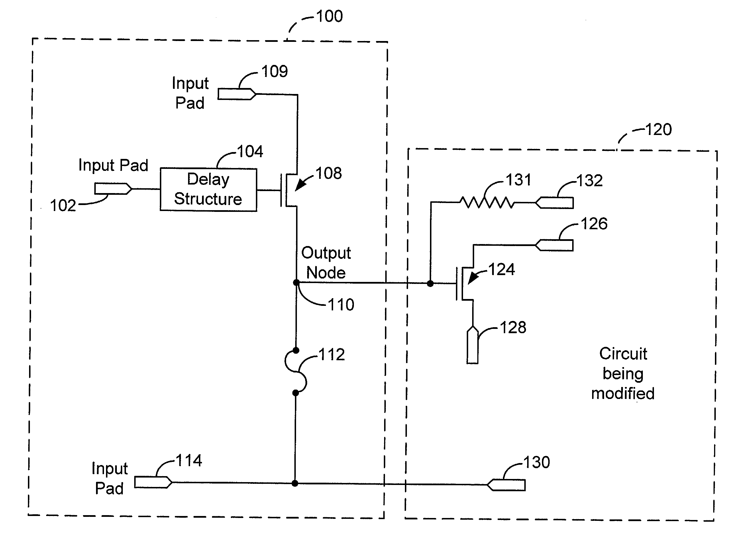
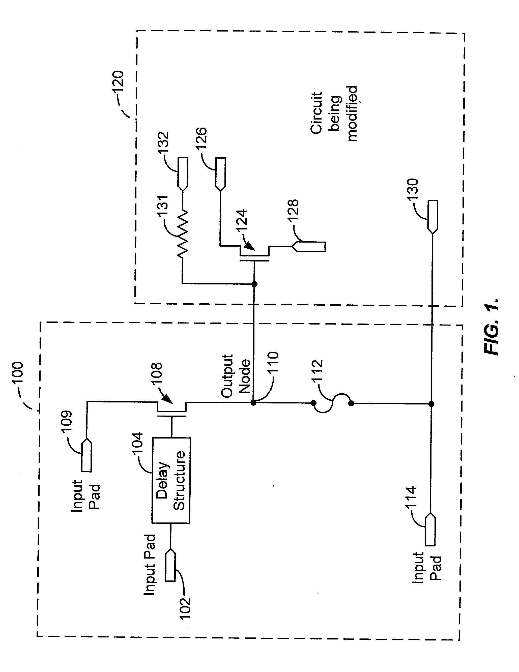
[0024] FIG. 1 shows a simplified high-level block diagram of an exemplary trimming circuit 100, according to an embodiment of the present invention. Trimming circuit 100 includes an input pad 102 configured to receive a select signal (also referred to hereinafter as a trigger signal) and includes a delay structure 104 coupled with input pad 102. Delay structure 104 is configured to add a delay to the trigger signal. Trimming circuit 100 also includes a transistor 108 coupled with delay structure 104. The exact dimensions of transistor 108 will depend on the specific application. Transistor 108 is sized to provide sufficient current to trim a metal or polysilicon trimming fuse. Transistor 108 couples between an input pad 109 and an output node 110. Input pad 109 is configured to receive a first voltage potential. In this particular embodiment, the first voltage potential is VDD. VDD can be a variety of voltages, e.g., 3 volts, 5 volts, 12 volts, etc. Typically, VDD is 3.3V. A trimmin...


PUM


Abstract

A method and apparatus for implementing trimming circuits. More particularly, embodiments of the present invention provide a transistor that supplies sufficient current to trim a trimming fuse when the transistor is powered up and after it receives a select signal at its gate. When the trimming fuse is trimmed, it decouples undesired electrical connections in a circuit. Also provided is a delay structure that adds an RC delay to the select signal. The RC delay is of a sufficiently long duration so as to decrease the switching speed of the transistor. The delay structure also provides a pass filter to filter power and voltage spikes in the select signal.

Description

[0001] The present invention relates generally to integrated circuits. More particularly, embodiments of the invention relate to a method and apparatus for implementing trimming circuits.[0002] Trimming circuits are used to configure and fine-tune IC products to meet final specification requirements. Such a trimming process typically occurs during the final stages of production. ICs are typically constructed with redundant circuit elements that are enabled or disabled by eliminating certain connections. The trimming process should reliably disengage undesired electrical connections while securely maintaining connections at other locations, as needed, for the lifetime of the product. Hereinafter, fuses are also referred to as trimming fuses.[0003] One common method used for trimming involves intentional loading of certain metal structures--fuses--with current well beyond the carrying capability of the fuse line. This results in vaporization of the metal and electrical discontinuity. ...

Claims


Application Information

Patent Timeline
IPC IPC(8): G11C17/18
CPCG11C17/18
Inventor SZABO, ANDRASOJALA, PEKKA
Owner EXAR CORP
Why Eureka
Try Eureka