
System and method for detecting and estimating the direction of near-stationary targets in monostatic clutter using phase information

Inactive Publication Date: 2003-10-09
RAYTHEON CO
View PDF0 Cites 32 Cited by
  • Summary
  • Abstract
  • Description
  • Claims
  • Application Information

AI Technical Summary

Problems solved by technology

Radio frequency (RF) detection of slowly moving or stationary targets in monostatic clutter is a problem that has recently generated a great deal of interest within the Defense cornmunity.
Monostatic clutter is particularly troublesome when trying to detect slowly moving target, since there is almost no Doppler difference between the clutter and the target.
The root of the difficulty lies in the fact that conventional radar systems use Doppler information for detection and tracking functions.
In the presence of clutter, conventional Doppler radar systems lose the ability to use the target's Doppler to discriminate it from the clutter.
Indeed, the target need not even be nearly stationary for this to be a problem.
However, the inclusion of these seeker modes increases development and production costs of the host platform.
Further, IR seekers exhibit more significant atmospheric limitations (smoke, fog, snow, and / or rain, etc.).

Method used


Image

  • System and method for detecting and estimating the direction of near-stationary targets in monostatic clutter using phase information
  • System and method for detecting and estimating the direction of near-stationary targets in monostatic clutter using phase information
  • System and method for detecting and estimating the direction of near-stationary targets in monostatic clutter using phase information

Examples


Embodiment Construction

[0033] Illustrative embodiments and exemplary applications will now be described with reference to the accompanying drawings to disclose the advantageous teachings of the present invention.

[0034] While the present invention is described herein with reference to illustrative embodiments for particular applications, it should be understood that the invention is not limited thereto. Those having ordinary skill in the art and access to the teachings provided herein will recognize additional modifications, applications, and embodiments within the scope thereof and additional fields in which the present invention would be of significant utility.

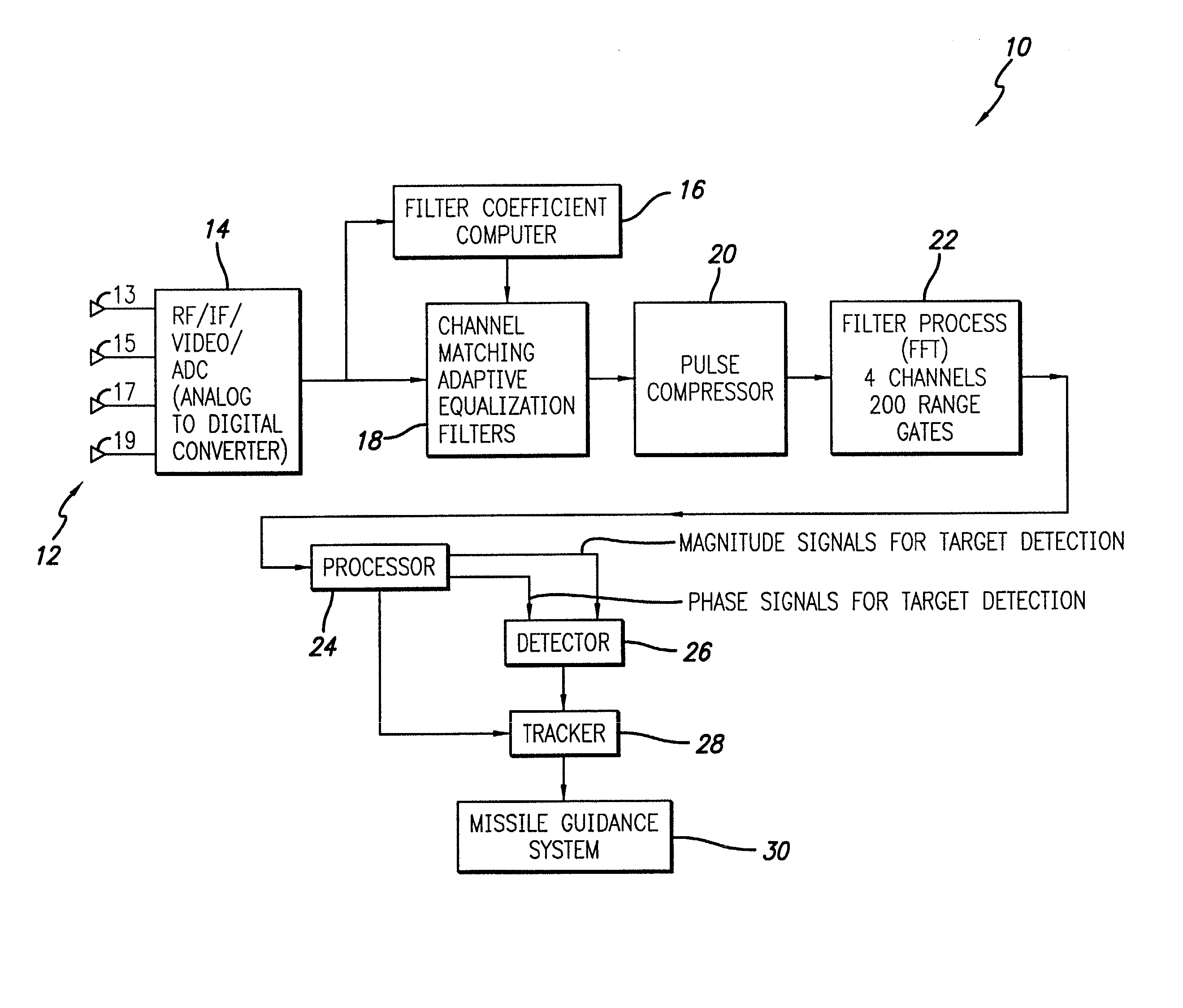
[0035] In conventional monopulse radio frequency (RF) seekers, only the amplitudes of the complex-valued range / Doppler-filter outputs are used for target detection and / or identification. The random-like phases of the range / Doppler-filter output values are seldom considered helpful for this purpose. However, as stated by Rihaczek and Hershkowitz in ...


PUM


Abstract

A system and method for detecting a target. The inventive method includes the steps of receiving a complex return signal of an electromagnetic pulse having a real and an imaginary component; extracting from the imaginary component information representative of the phase component of the return signal; and utilizing the phase component to detect the target. Specifically, the phase components are those found from the complex range-Doppler map. More specific embodiments further include the steps of determining a power spectral density of the phase component of the return signal; performing a cross-correlation of power spectral density of the phase component of the return signal between different antenna-subarray (quadrant channels); and averaging the cross-correlated power spectral density of the low frequency components. In an alternative embodiment, the cross-correlation is performed on the phase component of the range-Doppler map directly. This signal can then be averaged to potentially provide improved detection of targets. The cross-correlations of the power spectral densities derived from the complex valued range-Doppler map are then used to detect the target in the presence of monostatic clutter. An additional teaching relates to a utilization of the phase component to ascertain a direction of the target and thereby effect target tracking as well as target detection.

Description

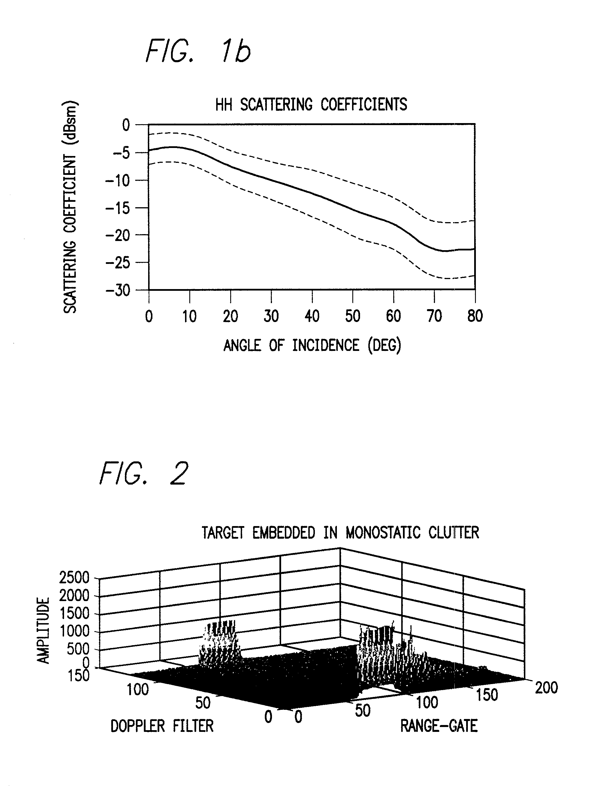
[0002] 1. Field of the Invention[0003] The present invention relates to electromagnetic seekers. More specifically, the present invention relates to systems and methods for detecting and tracking targets in clutter.[0004] 2. Description of the Related Art[0005] Radio frequency (RF) detection of slowly moving or stationary targets in monostatic clutter is a problem that has recently generated a great deal of interest within the Defense cornmunity. Monostatic clutter is naturally produced by ground reflections of the radar's transmitted signal. Monostatic clutter is thus largest at zero relative Doppler. Monostatic clutter is particularly troublesome when trying to detect slowly moving target, since there is almost no Doppler difference between the clutter and the target. Exemplary targets include surface vehicles, launchers and loitering UAVs (Unmanned Airborne Vehicles). The root of the difficulty lies in the fact that conventional radar systems use Doppler information for detection...

Claims


Application Information

Patent Timeline
IPC IPC(8): G01S7/288G01S13/524G01S13/88
CPCG01S13/5244G01S2007/2886G01S2007/2883G01S13/883G01S7/2886G01S7/2883
Inventor CHEN, HAI-WAISCHMITT, HARRY A.DAVID, GEORGE T.BRAUNREITER, DENNIS C.SAMUEL, ALPHONSO A.DAVID, JUDITH L.
Owner RAYTHEON CO
Learn More