
Multicolour and multiple material injection moulding of a capsule provided with a cap pivoting about a hinge

a multi-material, capsule technology, applied in the direction of manufacturing tools, transportation and packaging, other domestic objects, etc., can solve the problems of limited decorative possibilities, thumb, and difficulty in using tubes, and achieve the effect of high melting temperature, efficient support, and increased surface area

Inactive Publication Date: 2003-09-25
CEBAL SA
View PDF0 Cites 10 Cited by
  • Summary
  • Abstract
  • Description
  • Claims
  • Application Information

AI Technical Summary

Benefits of technology

[0023] The gate must be placed to satisfy a number of criteria; firstly this position determines the boundary between the two materials and the geometric configuration in which the two materials will come into contact. Even if you choose two materials with compatible bonding and / or melting temperatures, it is preferable to aim at a certain interpenetration of the materials to improve bond. Furthermore, as described in FR 2 662 144 and EP 0 826 606, it is recommended that this boundary should be located in an area with low mechanical stresses, particularly in fatigue.
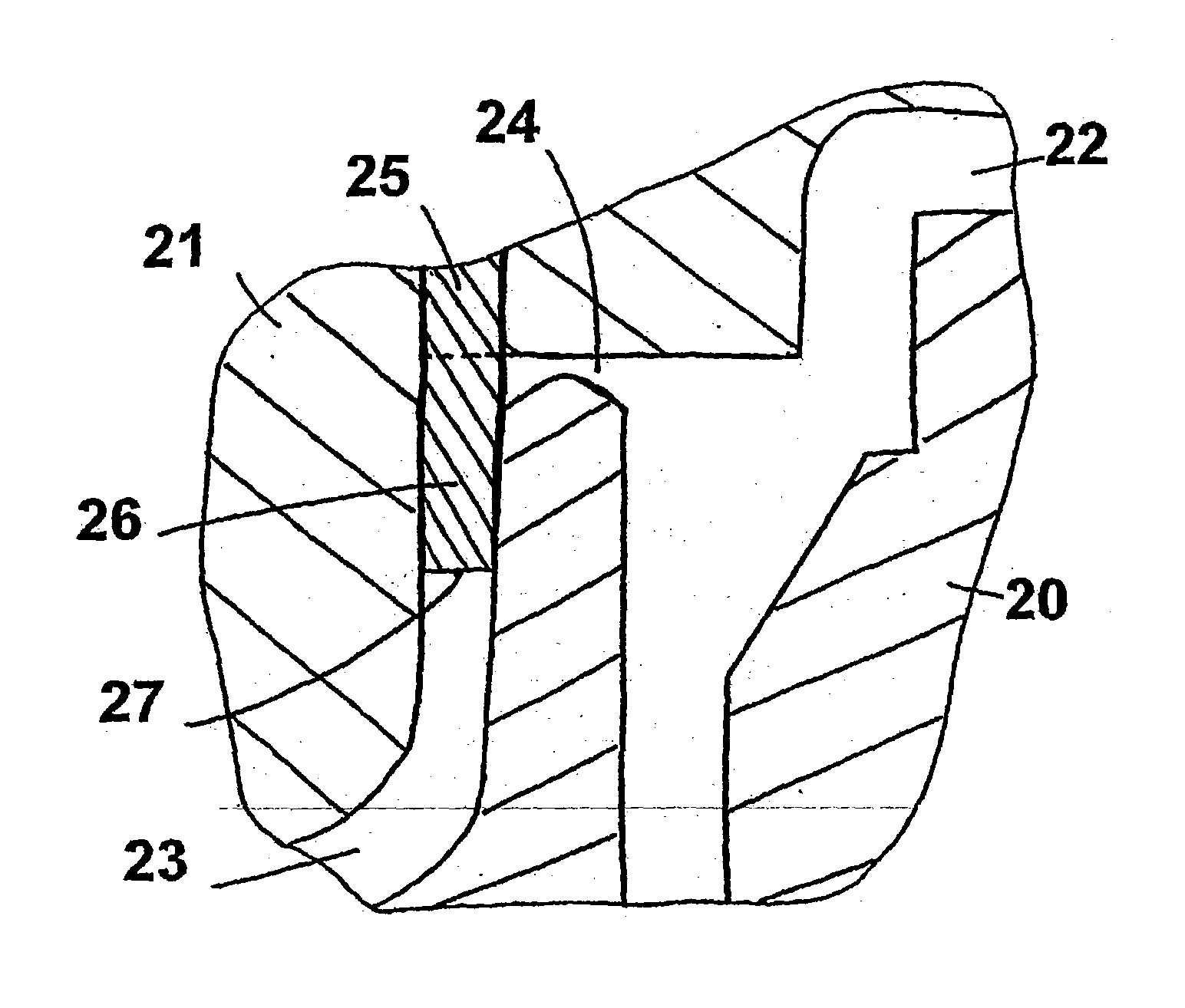
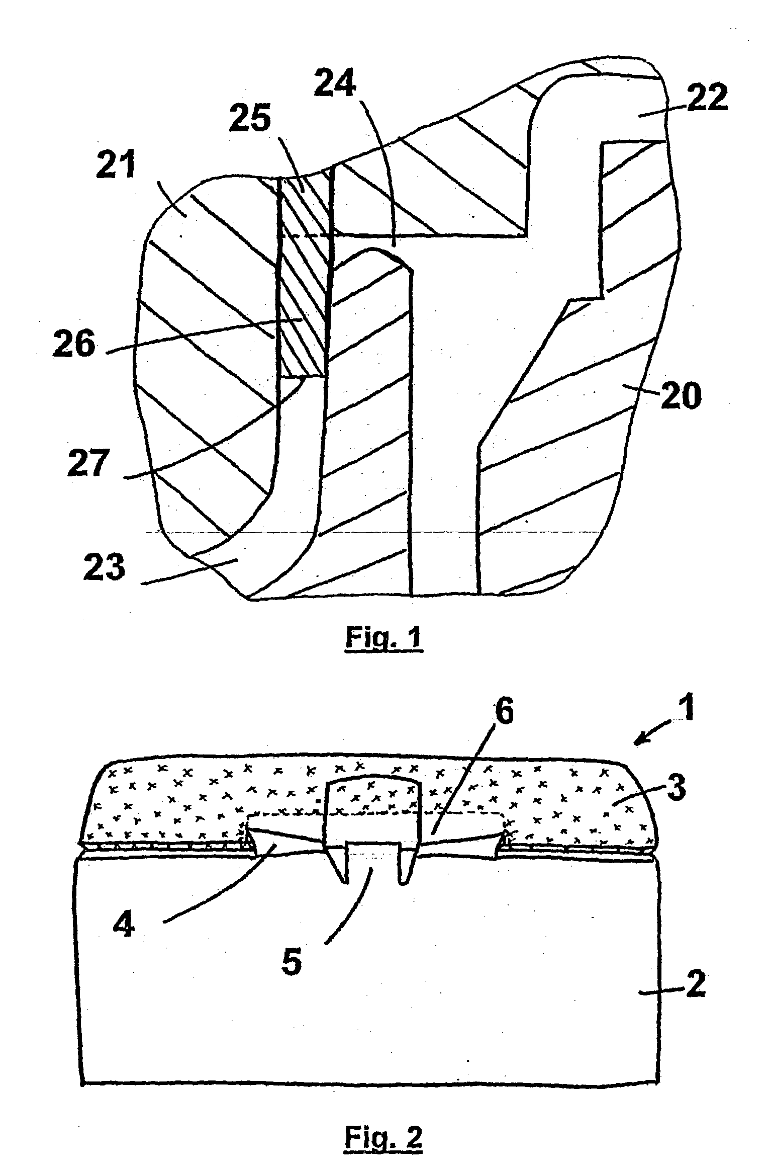
[0028] Unfortunately, this natural choice consisting of putting a gate at depth in the part of the vertical wall of the cap, does not produce the required effect, since the boundary between the plastic materials is not at the required location; it allows the plastic material in the base to rise significantly into the cap area and thus destroys the required impression of a clear cut separation between the base and the cap. FIG. 2 illustrates the visual appearance achieved.
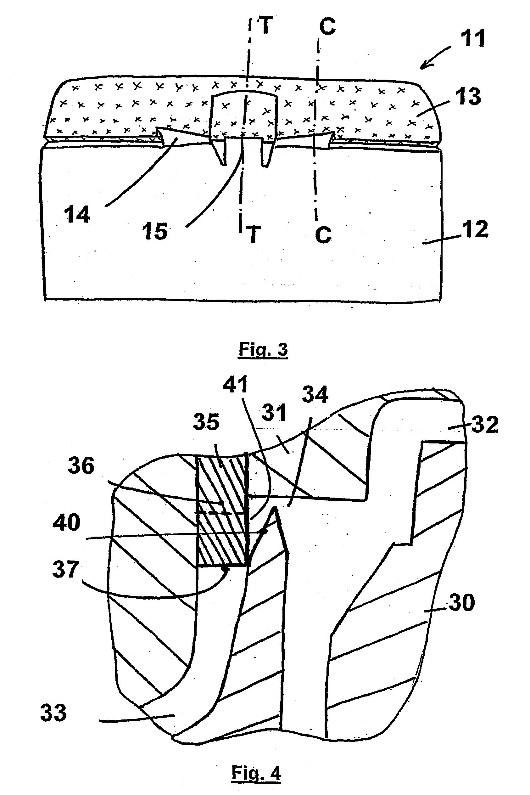
[0029] To solve this problem, the applicant reversed the sequence of the injections, increased the surface area of the fasteners of the hinge elements on the cap and modified the shape of the gate, which is no longer a simple prism matching the thickness of the wall of the cap, but is now a three-dimensional part with a height and possibly a thickness that are different at the tensioning element of the hinge and at the film hinge. The slope of the oblique wall of the second mould, corresponding to the cavity of the film hinge fastener and the tensioning element on the cap, is significantly increased such that the height of this fastener is at least twice the thickness of the tensioning element.
[0031] As soon as the first plastic material has been injected, the gate is raised and the plastic material of the cap is injected. This second plastic material comes into contact with the first plastic material that is still hot at the level of the fasteners of the hinge elements, for which the height according to the invention was significantly increased. Thus, the height at the fastener of the tensioning element is equal to approximately twice the average thickness of this element. The height of the film hinge fastener is exactly the same as the height of the tensioning element fastener, so that the conditions for interpenetration of the plastic materials can be made uniform along all parts of the hinge. The increase in the height of the fastener has little influence on the mechanical behaviour of the film hinge since the thickness of the film hinge was already not uniform with a preferred bending zone, even before the modifications according to the invention were made, but this is not true for the tensioning element which is significantly stiffer at the location of the fastener. However, despite its greater stiffness at the attachment on the cap, this tensioning element continues to play its driving role as the cap rotates. The fact that the fasteners of the hinge elements are higher on the cap provides a larger spatial configuration of the cavity that is more conducive to mix of the two plastic materials, by reducing the shear necessary to obtain a good bond between the said plastic materials.
[0032] To improve interpenetration of plastic materials with each other, the front wall of the gate varies in height; when the gate is raised in the open position, the front wall does not rise up inside the upper equipment but remains slightly projecting, which means that there is a smooth transition between the thickness of the relatively thick and approximately vertical wall of the cap and the thickness of the fastener. The fact of leaving the gate projecting slightly at the hinge means that the hinge cannot be deformed; the part of the gate that remains projecting occupies the place of a thick portion of the cap, which if it had been formed with the injected plastic material, would have imposed a significant deformation of the hinge and the base of the capsule during its shrinkage, resulting in an overthickness of the said capsule base which would prevent good closure of the cap on the base.
[0033] Finally, the height of the gate at the tensioning element is such that it can close off the cavity of the fastener in the closed position. The only thing necessary is for the gate front wall to drop slightly below the fastener since the thrust of the first plastic material is lateral and the bearing can be made by the other transverse wall, and to bear directly on the core of the first mould used to make the inside of the cap.

Problems solved by technology

However, the cap which is moulded simultaneously with the rest of the tube, is obviously made of the same material, which firstly limits the decorative possibilities of the capsule in that it is obliged to have the same monotonous, everyday and even inesthetic appearance, and also makes it more difficult to use the tube due to the rigid nature of the cap which is cold to touch and not very pleasant, and could even injure the user's thumb if the relief on the gripping projection of the cap is excessively pronounced.
Therefore, there is a problem of mechanical strength, particularly in fatigue, of elements of the hinge located close to bonding between the materials.

Method used


Image

  • Multicolour and multiple material injection moulding of a capsule provided with a cap pivoting about a hinge
  • Multicolour and multiple material injection moulding of a capsule provided with a cap pivoting about a hinge
  • Multicolour and multiple material injection moulding of a capsule provided with a cap pivoting about a hinge

Examples


example 1

[0041] (FIGS. 1 and 2)

[0042] The bi-colour service capsule 1 comprises a cap 3 made of a first plastic material and a base 2 made of a second plastic material, both being connected together by hinge elements consisting of two film hinges 4 and a tensioning element 5.

[0043] In the conventional process used to make this two-colour capsule, the moulding equipment comprises two moulds, the first mould 21 and the second mould 20. A mobile part, the gate 25, slides insides the first mould 21, along the continuation of the approximately vertical part of the cavity 23 used for moulding the cap, and the front wall 27 of the gate must descend deeply into the cavity 23, to several millimetres below the cavity 24 corresponding to the hinge, leaving a zone 26 not filled by the plastic material of the cap.

[0044] The sequential dual injection process using this moulding equipment and in which the plastic material (transparent polypropylene) of the cap is injected before the opaque polypropylene of...

example 2

[0045] (FIGS. 3, 4 and 5)

[0046] The two-colour service capsule 11 comprises a base 12 made of a first plastic material and a cap 13 made of a second plastic material, both being connected to each other by hinge elements consisting of two film hinges 14 and a tensioning element 15.

[0047] In the process according to the invention used to make this two-colour capsule 11, the moulding equipment comprises two moulds, the first mould 31 and the second mould 30. The first step is to inject the base and then the cap.

[0048] A mobile part called the gate 35 is free to slide inside the first mould 31, along the continuation of the approximately vertical part of the cavity 33 used to mould the cap, and the front wall 37 of the gate does not descend deeply into the cavity 33. The sections in FIGS. 4 and 5 made along C-C and T-T respectively, show that the gate 35 is thicker at the film hinge than at the tensioning element. The heights of the fasteners of the hinge elements have been increased an...


PUM

PropertyMeasurementUnit
Fractionaaaaaaaaaa
Angleaaaaaaaaaa
Thicknessaaaaaaaaaa

Abstract

The invention concerns a method for sequential moulding with multiple materials for making a piece comprising at least two parts with matching shapes produced in a different plastic material, mobile relative to each other by pivoting about a hinge, which consists in: using a moulding equipment comprising a second mould (30) and a first mould (31) whereof the assembled impressions define the cavity of the open part, the mobile portions forming between them an angle of about 180°, one of the moulds (31) comprising a housing wherein slides a gate (35), capable of blocking the flow of the first plastic material; injecting the first portion (32, 34) with a first plastic material, the gate (35) providing with its side wall an obstacle to the flow of said first plastic material at the fasteners of the elements of the hinge on the second piece; causing the gate (35) to open and injecting the second plastic material into the second portion (33) of the piece.

Description

[0001] The invention relates to a moulding process for capsules that will be fixed on containers such as flexible tubes, bottles or tottles. The said capsules are provided with a pivoting cap that closes a distribution orifice. This type of container will be used to store and distribute fluid, cream or paste materials generally used for cosmetics, food, household, pharmaceutical or parapharmaceutical. We will use the general term "tubes" throughout the rest of this description to denote all of these containers.STATE OF THE ART[0002] With capsules fitted with a pivoting cap, the consumer can manipulate the tube with a single hand and be sure he or she will not lose the lid, since it is very easy to put the lid down and accidentally lose it after detaching it to release the distribution orifice. This type of capsule became much more widely used when it became possible to mould them in a single part, with the consequence of significantly reducing their manufacturing cost.[0003] Capsule...

Claims


Application Information

Patent Timeline
IPC IPC(8): B29C45/16B65D47/08
CPCB29C45/1639B65D47/08B29L2031/565
Inventor SCHNEIDER, BERNARD
Owner CEBAL SA
Learn More