
Method and apparatus for mounting

a technology of mounting method and mounting apparatus, applied in the direction of mechanical control device, paper/cardboard container, instruments, etc., can solve the problems of local fine gap, damage to bonding reliability, and inability to find the method of adjusting or correcting the parallelism within a high accuracy during bonding

Inactive Publication Date: 2003-09-11
TORAY ENG CO LTD +1
View PDF2 Cites 62 Cited by
  • Summary
  • Abstract
  • Description
  • Claims
  • Application Information

AI Technical Summary

Benefits of technology

[0012] Further, the above-described temporary bonding and final bonding may be carried out in a pressure-reduced gas atmosphere. Alternatively, the temporary bonding and final bonding may be carried out in a special gas atmosphere. The special gas in the present invention means, for example, an inert gas such as argon gas, a gas such as nitrogen gas which does not react with the objects, a gas which can replace the surface oxides to fluoro groups and the like on the surfaces of the objects, a gas which contains hydrogen and can react at a reducing condition on the surfaces of the objects, or a gas which contains oxygen and can remove carbons (organic substances) on the surfaces of the objects. If the temporary bonding and final bonding are carried out in such a special gas atmosphere, it becomes possible to suppress oxidation at the bonded portion between the objects and to prevent a reaction and adhesion of contamination which may obstruct the bonding.
[0013] Such a mounting method according to the present invention can be appropriately applied also to a room-temperature bonding method aforementioned. Namely, after the surfaces of both objects to be bonded to each other are cleaned by irradiating an energy wave or energy particle beam, the cleaned surfaces of both objects can be bonded to each other at a room temperature by the above-described method. As the used energy wave or energy particle beam, for example, a plasma (including an atmospheric-pressure plasma), an ion beam, an atomic beam, a radical beam or a laser can be employed. In case of such an application to a room-temperature bonding method, the cleaning may be carried out in a pressure-reduced gas atmosphere to increase the effect of the cleaning. However, when an enough effect can be obtained by the cleaning at an atmospheric pressure, the pressure reduction is not necessary.
[0019] Furthermore, the above-described mounting apparatus may have a cleaning chamber equipped with means for irradiating an energy wave or energy particle beam for cleaning the surfaces of both objects to be bonded to each other. In such a structure, the aforementioned room temperature bonding becomes possible. Moreover, even if the room temperature bonding is not required, because it becomes possible to remove the oxides and organic substances from the surfaces of the objects by irradiating the energy wave or energy particle beam, it becomes possible to maintain the surfaces of the objects before bonding to be in a clean condition, thereby achieving a more reliable bonding. As the energy wave or energy particle beam, for example, a plasma, an ion beam, an atomic beam, a radical beam or a laser can be used. Also to this cleaning chamber, a vacuum pump is attached for reducing a pressure in the chamber, and by the cleaning under the pressure-reduced condition, a further effective cleaning becomes possible. Further, it is also possible to attach a gas replacing means to the cleaning chamber for creating a special gas atmosphere in the chamber, for example, an inert gas replacing means for creating an inert gas atmosphere, and to carry out the cleaning under such a gas atmosphere condition. In a case where both the cleaning chamber and the bonding chamber are provided, it is preferred to provide a shutter means being opened and closed at a position between both chambers.
[0020] In the above-described mounting method and apparatus according to the present invention, an extremely high-accuracy and reliable bonding can be achieved finally by carrying out the temporary bonding at a condition adjusted in parallelism and thereafter carrying out the final bonding by pressing the temporarily bonded objects against the reference positioning surface of the backup member. Further, the mounting method and apparatus can be appropriately applied also to the room temperature bonding for cleaning the surfaces by irradiating the energy wave or energy particle beam prior to the bonding.

Problems solved by technology

Although various methods for achieving a high-accuracy alignment have been proposed, most of them aim to control the parallelism between objects within a predetermined accuracy immediately before bonding, and methods for adjusting or correcting the parallelism within a high accuracy during bonding are not found.
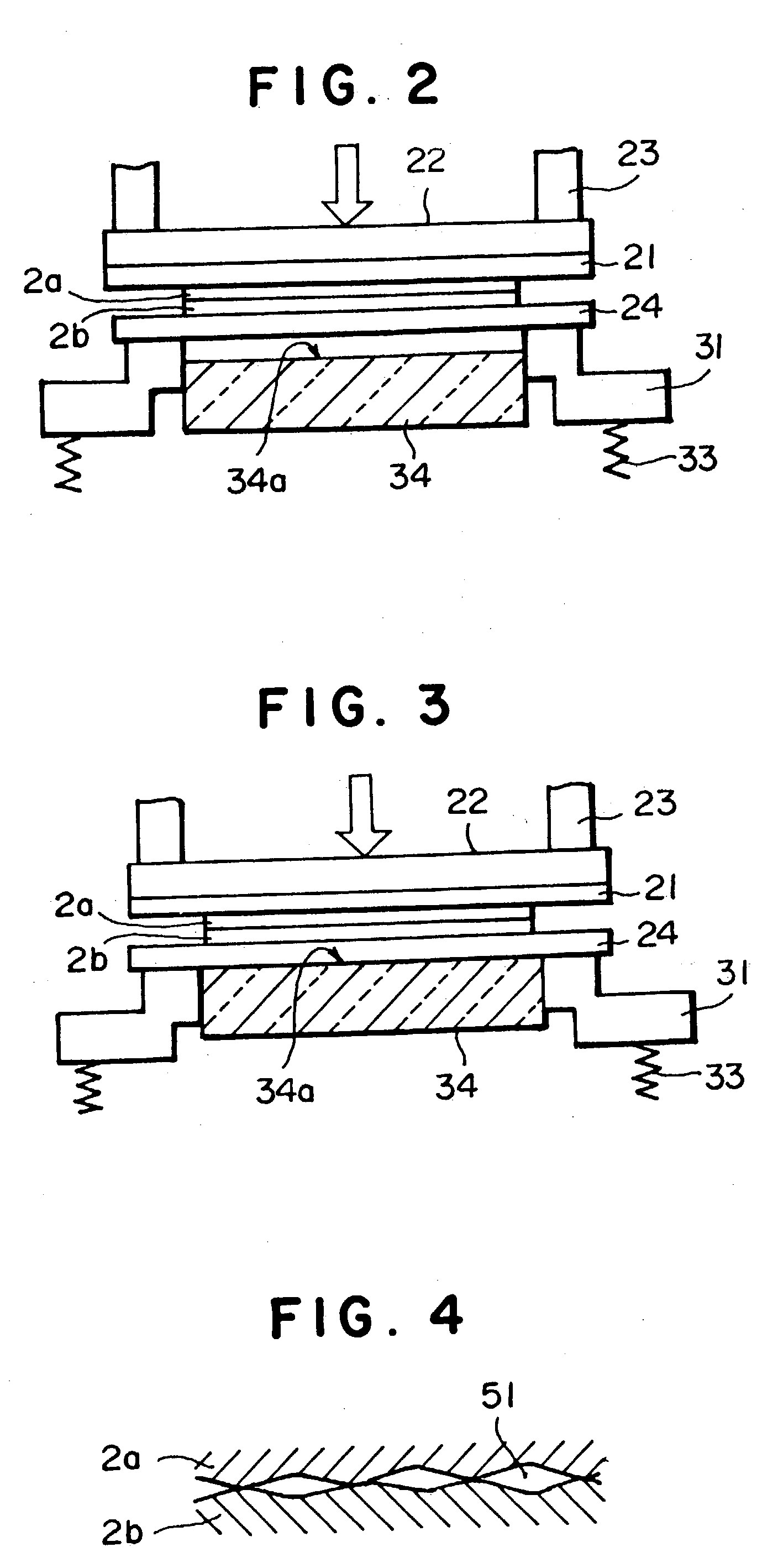
Further, although it is possible to bond the surfaces activated as described above at a room temperature merely by bringing the surfaces into contact with each other, in a case where there are fine irregularities on the surfaces of the objects, especially in a case where concave portions are stacked to each other, there may occur a local fine gap because the strong bonding force between the activated atoms cannot operate at such a position.
The presence of such a fine gap may damage the reliability of bonding.

Method used


Image

  • Method and apparatus for mounting
  • Method and apparatus for mounting
  • Method and apparatus for mounting

Examples


Embodiment Construction

[0026] Hereinafter, desirable embodiments of the present invention will be explained referring to figures.

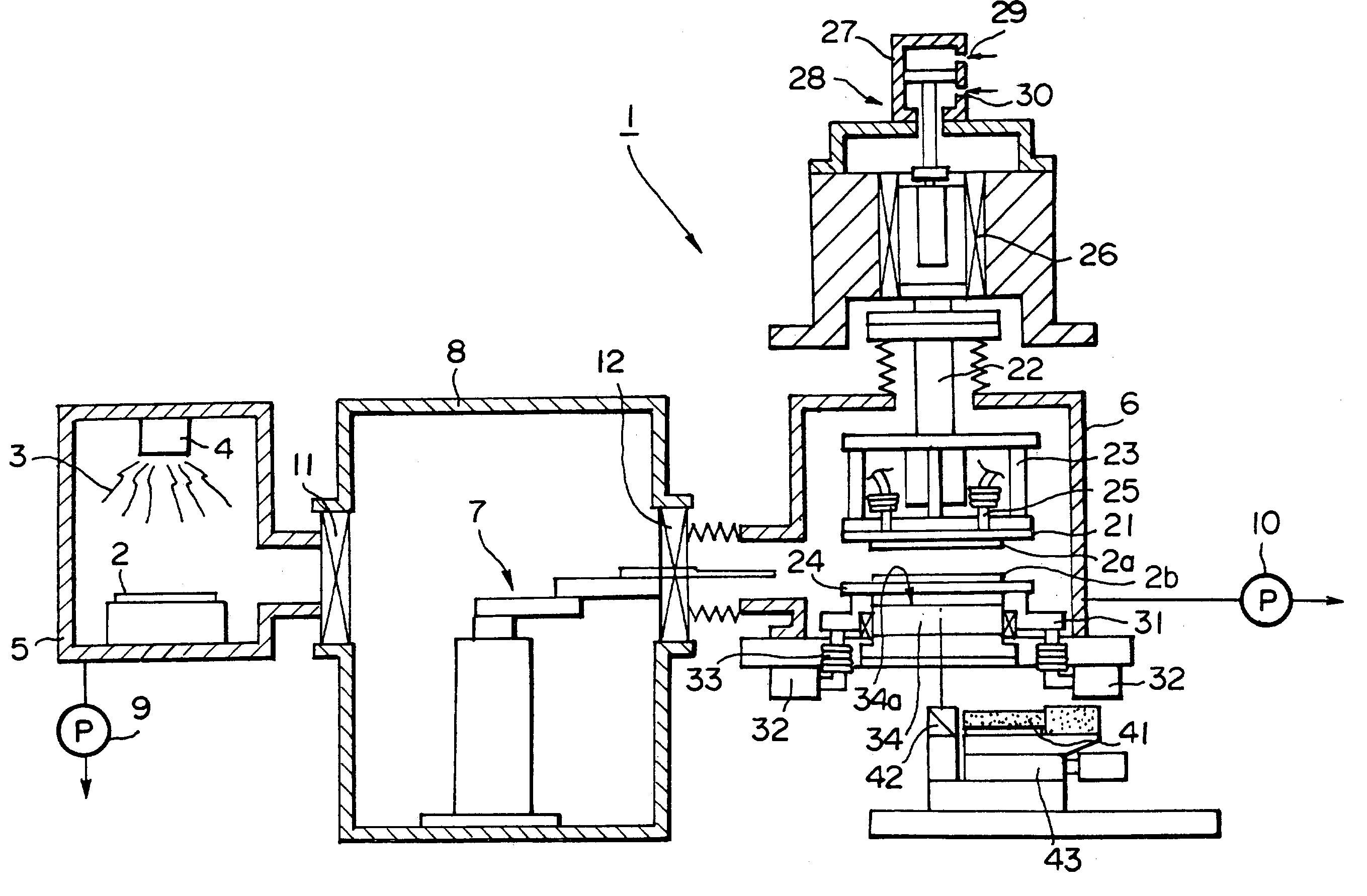
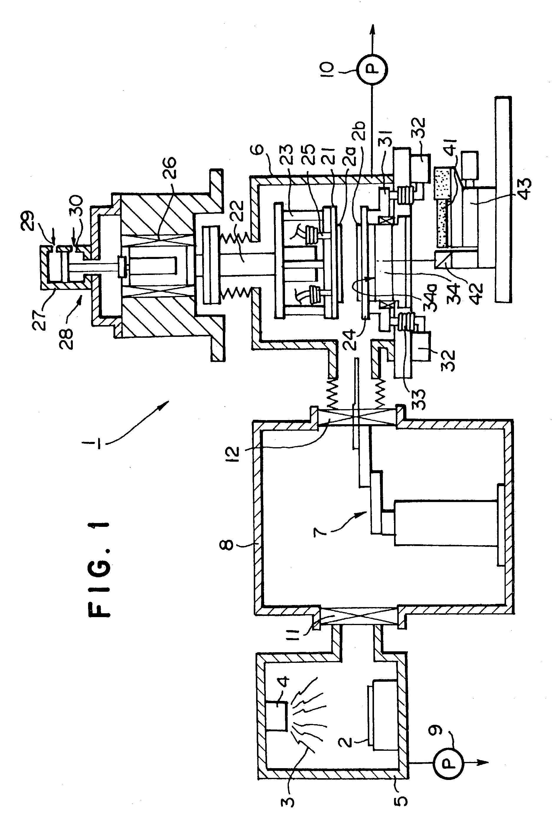
[0027] FIG. 1 shows a mounting apparatus according to an embodiment of the present invention. In FIG. 1, numeral 1 indicates the entire mounting apparatus, and FIG. 1 shows a case where wafers provided as objects are bonded to each other. In this embodiment, mounting apparatus 1 has a cleaning chamber 5 equipped with an energy wave irradiating means 4 (or an energy particle beam irradiating means) for irradiating an energy wave 3 onto the surfaces of the objects in order to clean the surfaces of wafers 2 provided as the objects to be bonded, a bonding chamber 6 for bonding a first object 2a and a second object 2b, and a conveying path 8 or a conveying chamber having a conveying robot 7 for conveying the cleaned first object 2a or first object 2a and second object 2b from the cleaning chamber 5 into the bonding chamber 6.

[0028] As the above-described energy wave or energy particl...


PUM

PropertyMeasurementUnit
distancesaaaaaaaaaa
pressureaaaaaaaaaa
temperatureaaaaaaaaaa

Abstract

A method and an apparatus for mounting: the method for bonding a plurality of objects to each other, comprising the steps of disposing, apart from each other, a first object, a second object and a holding means therefor, and a backup member having a reference positioning surface in this order, adjusting the parallelism of the second object or the holding means therefor relative to the reference positioning surface, adjusting the parallelism of the first object or the holding means therefor relative to the second object or the holding means therefor, bringing the first object into contact with the second object to temporarily bond both objects to each other, bringing the holding means for the second object into contact with the reference positioning surface of the backup member, and pressing both objects against each other for final bonding, whereby, finally, a highly reliable and accurate bonding state can be achieved.

Description

[0001] The present invention relates to mounting method and apparatus for bonding a plurality of objects such as wafers to each other.BACKGROUND ART OF THE INVENTION[0002] When a plurality of objects such as wafers, chips and substrates are bonded to each other, a high accuracy in parallelism between both objects to be bonded is required immediately before bonding or at the time of bonding. Recently, the requirement of the accuracy has been increased, and a high accuracy up to submicrons has been required. Although various methods for achieving a high-accuracy alignment have been proposed, most of them aim to control the parallelism between objects within a predetermined accuracy immediately before bonding, and methods for adjusting or correcting the parallelism within a high accuracy during bonding are not found.[0003] On the other hand, as a method for bonding objects to each other, Japanese Patent 2,791,429 discloses a room-temperature bonding method of silicon wafers for sputter...

Claims


Application Information

Patent Timeline
Patent Type & Authority Applications(United States)
IPC IPC(8): H01L21/00H01L21/02
CPCY10T156/10H01L21/67092H01L21/52
Inventor SUGA, TADATOMOYAMAUCHI, AKIRAARAI, YOSHIYUKIINAKA, CHISA
Owner TORAY ENG CO LTD
Learn More