
Network analyzer for measuring the antenna return loss in a live cellular network

a network analyzer and live cellular network technology, applied in the field of test and measurement systems, can solve the problems of reducing call quality, signal has the potential to disrupt the existing radio link between the base station and the mobile phone of customers, and high level of interference at the input to the base station receiver

Inactive Publication Date: 2003-08-07
AGILENT TECH INC
View PDF3 Cites 33 Cited by
  • Summary
  • Abstract
  • Description
  • Claims
  • Application Information

AI Technical Summary

Problems solved by technology

However, if a "live" (i.e., currently in-use) test is required, the injected signal has the potential to disrupt the existing radio links between the base station and customers' mobile phones.
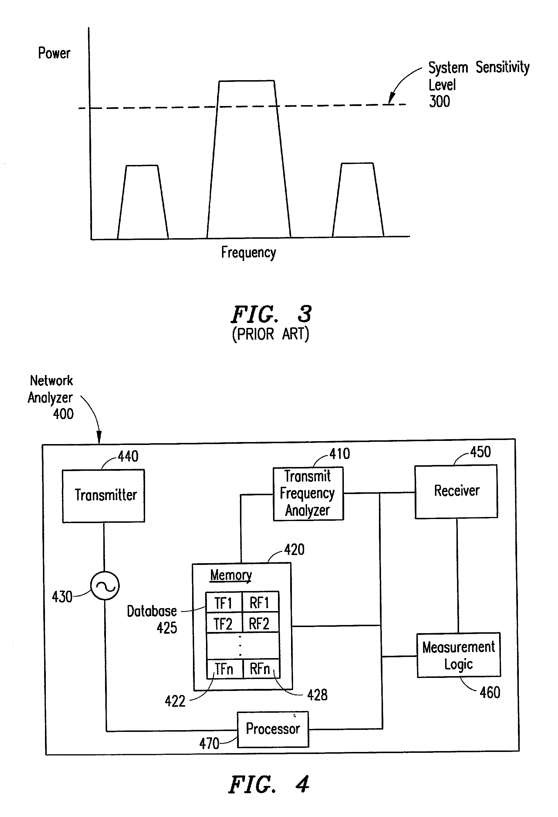
For example, when testing a receive antenna (i.e., an antenna operating at the base station receive frequencies), as the network analyzer's source sweeps through the channel that the mobile phone's transmitter occupies (i.e., up-link channel from the mobile phone to the base station), a high level of interference is experienced at the input to the base station receiver.
The interference could result in a reduction of the call quality, and possibly cause the call to drop.
However, by using the base station transmitter as the source, transmitted and reflected signal measurements can only be made on the frequencies at which the base station is actually transmitting.
Furthermore, without a broadband return loss measurement, the time-domain impulse response of the transmit antenna cannot be accurately calculated.
In addition, direct sequence spread spectrum modulation has the additional disadvantage of being relatively expensive to implement.

Method used


Image

  • Network analyzer for measuring the antenna return loss in a live cellular network
  • Network analyzer for measuring the antenna return loss in a live cellular network
  • Network analyzer for measuring the antenna return loss in a live cellular network

Examples


Embodiment Construction

[0023] The numerous innovative teachings of the present application will be described with particular reference to the exemplary embodiments. However, it should be understood that these embodiments provide only a few examples of the many advantageous uses of the innovative teachings herein. In general, statements made in the specification do not necessarily delimit any of the various claimed inventions. Moreover, some statements may apply to some inventive features, but not to others.

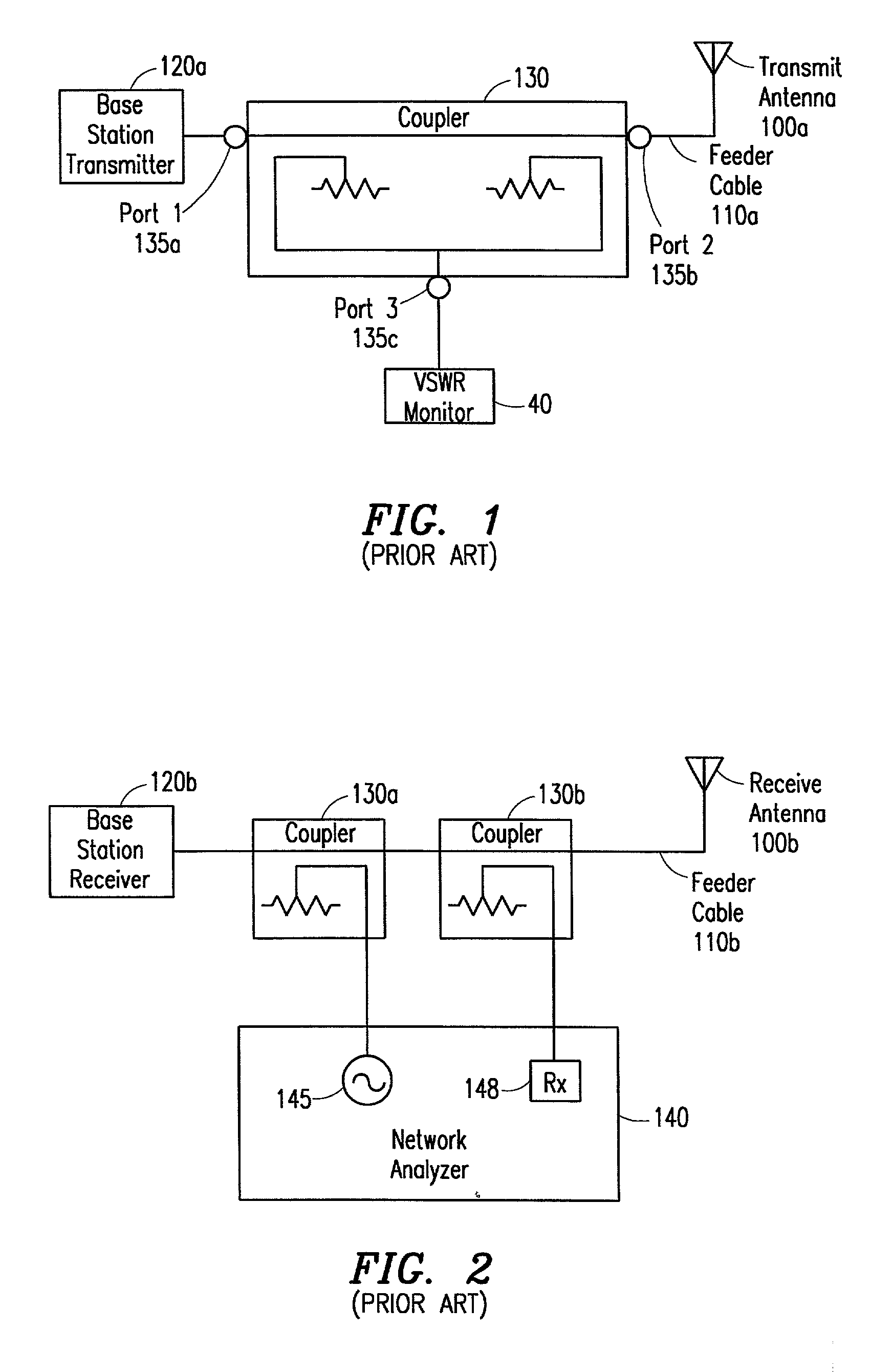
[0024] FIG. 1 illustrates a conventional VSWR 40 connected between a base station transmitter 120a and a transmit antenna 100a that uses the base station transmitter 120a as the source stimulus for measuring the antenna return loss on a transmit antenna 100a. The VSWR monitor 40 is shown connected to a coupler 130 that is placed on a feeder cable 110a between the base station transmitter 120a and the transmit antenna 100a. The coupler 130 has three ports 135a-c, in which the first port 135a receives the...


PUM


Abstract

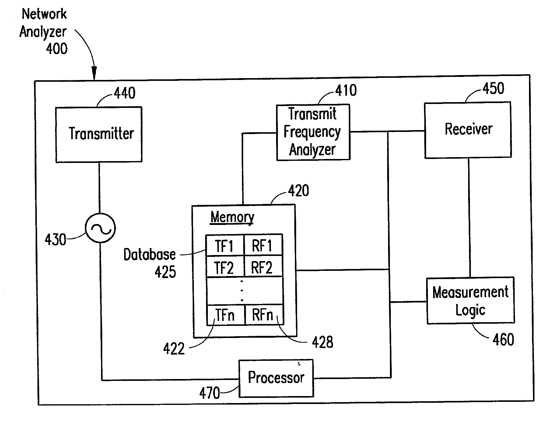
A network analyzer is capable of measuring the antenna return loss in a live cellular network. The network analyzer receives and analyzes the base station transmitted signal to determine which transmit frequencies are active. Based on information relating to the correlation between the transmit frequency and the associated receive frequency, the network analyzer determines the active receive frequencies. An unmodulated source that avoids inclusion of the active receive frequencies is generated by the network analyzer. To fill in the antenna sweep with the previously avoided frequencies, the network analyzer generates another source containing only those avoided frequencies when no calls are active on the avoided frequencies. Alternatively, the antenna return loss on the avoided frequencies is interpolated from the measured frequencies. As a further alternative, the network analyzer receiver determines a nearby frequency to an active frequency, and adaptively measures the nearby frequency as the avoided (active) frequency.

Description

[0001] 1. Technical Field of the Invention[0002] The present invention relates generally to test and measurement systems, and in particular, to network analyzers for measuring the antenna return loss of cellular base station antennas.[0003] 2. Description of Related Art[0004] Network analyzers measure the antenna return loss of a cellular base station antenna by injecting a swept signal covering the antenna transmit and / or receive frequencies into the device under test (DUT), i.e., antenna, and measuring the magnitude and phase of the signal that is reflected back. For example, typically, a technician connects the network analyzer to the feeder cable extending between the antenna and the base station, and injects a signal into the feeder cable. If there are any discontinuities in the feeder cable or antenna, part of the signal may be reflected back down the feeder cable to the network analyzer.[0005] Network analyzers are primarily utilized when the antenna being tested is not curre...

Claims


Application Information

Patent Timeline
IPC IPC(8): H04B7/26G01R29/10H04B17/00H04W24/00
CPCH04W24/00
Inventor NOE, TERRENCE R.
Owner AGILENT TECH INC
Learn More