Cold Gas Generator

a generator and cold gas technology, applied in the direction of pedestrian/occupant safety arrangement, transportation and packaging, vehicle safety arrangements, etc., can solve the problems of high filling pressure of storage devices, corresponding manufacturing-technological expenditure, and high filling pressure, so as to prevent an excessive deformation of the bursting disk, the limit or burst pressure is precisely adjusted, and the effect of high filling pressur

Inactive Publication Date: 2003-07-24
WELZ INDPROD
View PDF9 Cites 7 Cited by
  • Summary
  • Abstract
  • Description
  • Claims
  • Application Information

AI Technical Summary

Benefits of technology

0014] Advantageously, in the pressure relief opening a flow throttle, in particular, on the side facing away from the bursting disk, is provided. In this way, the pressure relief opening and the bursting disk can be configured with a correspondingly large surface area which results in a precise adjustability of the limit or burst pressure. At the same time, in an over pressure situation the flow throttle prevents, particularly in the case of helium as a filling gas, a release that is too fast because of the excellent flow properties of helium in combination with the high filling pressure possible with helium. As a result of the arrangement of the flow throttle on the side facing away from the bursting disk of the pressure relief opening, the bursting disk is not impaired by the flow throttle when bursting.
0015] Advantageously, the pressure relief opening is a cylindrical bore with a correspondingly large diameter. At the bottom of this bore, approximately coaxially thereto, a throttle bore with a matched smaller diameter is provided which forms the flow throttle. With this arrangement, the pressure relief opening together with the throttle bore can be drilled in a simple way in a single working step. The bore with the greater diameter has expediently a depth which corresponds at least approximately to half its diameter. In this way it is prevented that individual portions of the destroyed di

Problems solved by technology

The limited space available for mounting in a motor vehicle requires a configuration of the storage device as small as possible so that for a safe filling of an airbag in an accident situation a high filling pressure of the storage device is needed.
In the case of extreme heat development and, in particular, in the case of fire, the storage device can reach a gas pressure which exceeds the construction-defined limits causing an overload of the storage device.
For attachment of the combined filling and safety valve a complex geometri

Method used


Image

  • Cold Gas Generator
  • Cold Gas Generator
  • Cold Gas Generator

Examples


Embodiment Construction

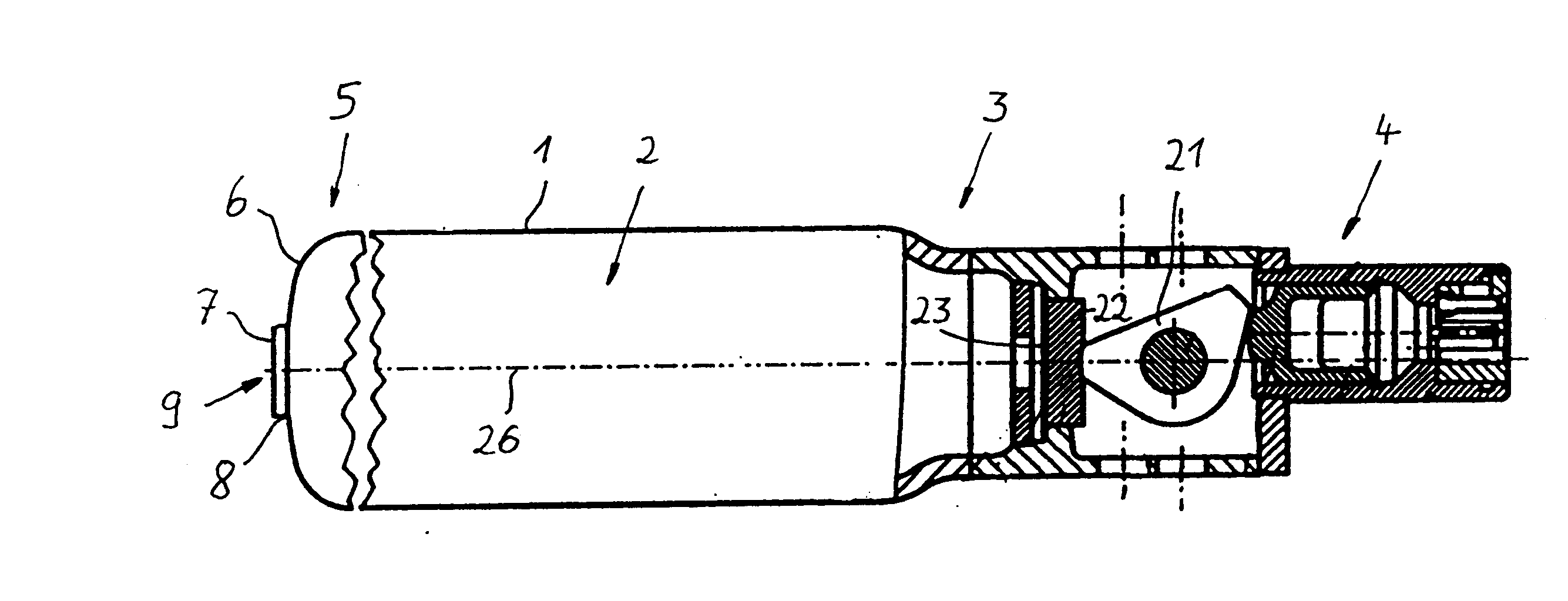
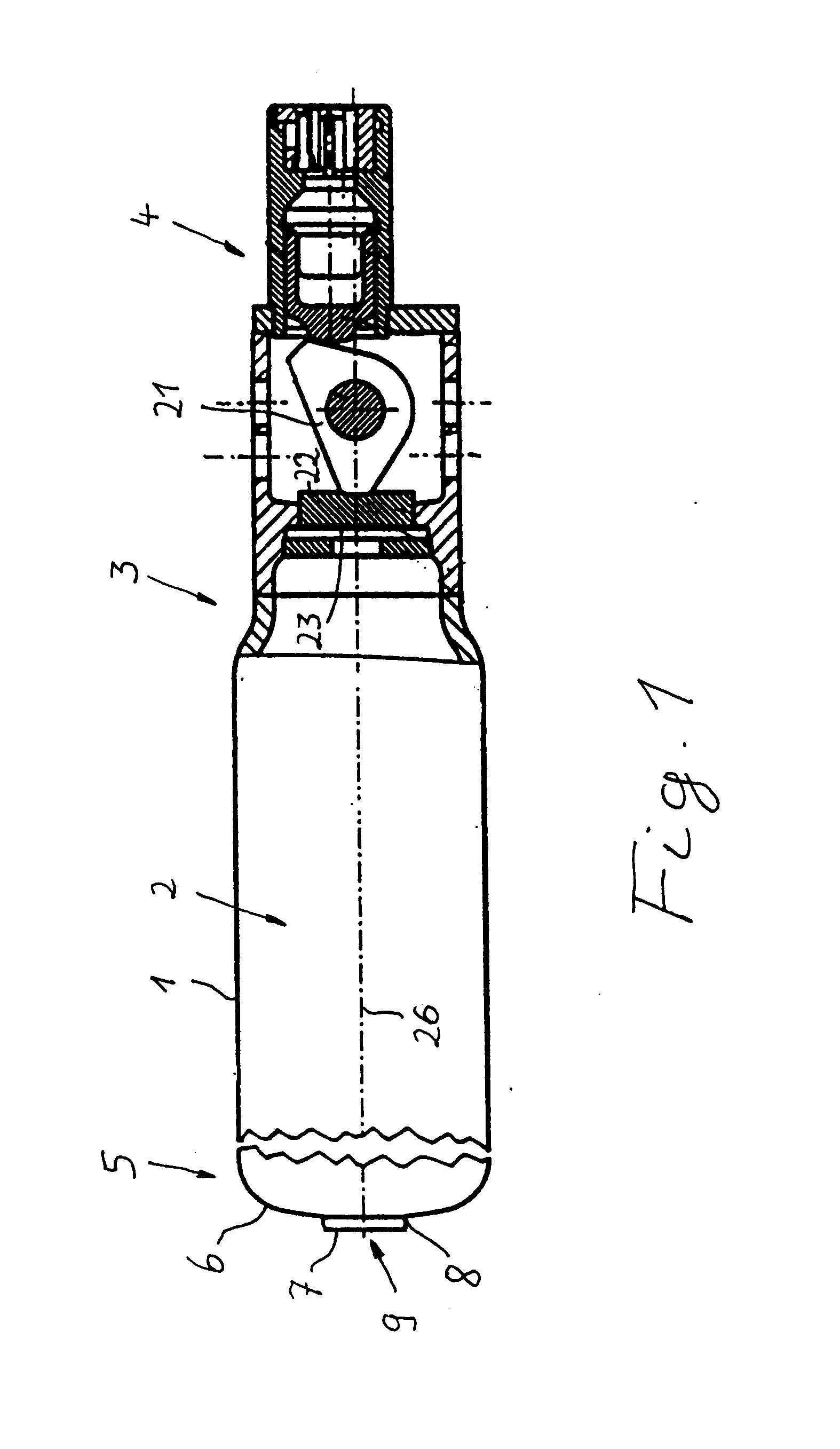
[0019] The overview illustration of Fig. 1 shows a cold gas generator for an airbag system in which a gas 2 is stored under pressure in a storage device 1. The gas is helium. At one end 3 of the storage device 1 having a substantially cylindrical configuration a triggering device 4 is provided which, when needed, acts on a support lever 21. A gas outlet opening 25 is closed by a sealing disk 23 in a gas-tight way wherein the sealing disk 23 is supported by an intermediate pressure plate 22 on the support lever 21. With an actuation of the triggering device 4 when needed, the support lever 21 is pivoted laterally wherein its support action on the pressure plate 22 and the sealing disk 23 is removed. The gas pressure acting on the sealing disk 23 bursts the sealing disk so that the gas 2 can flow into an airbag (not illustrated).

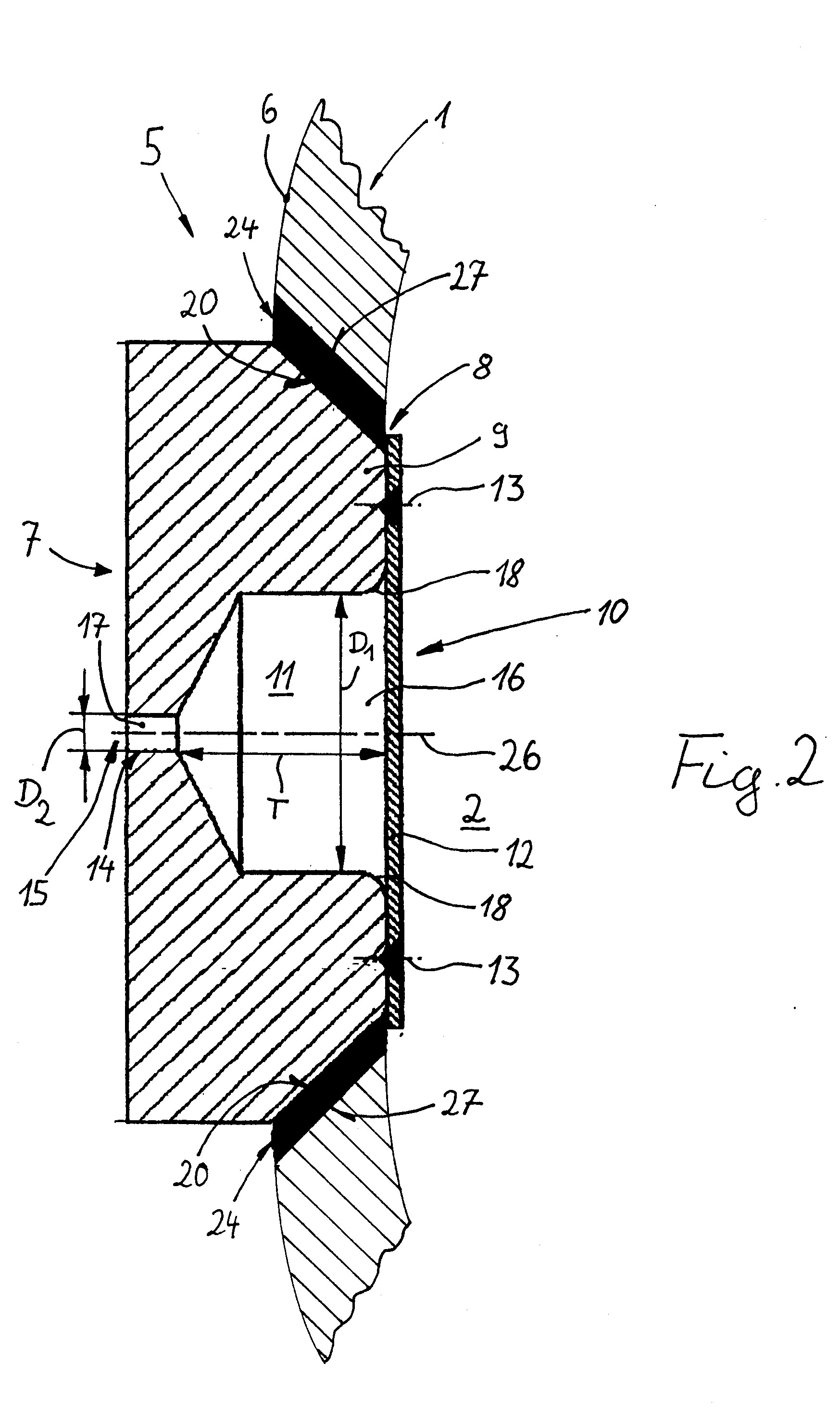
[0020] On the opposite end 5 of the storage device 1, a convexly curved bottom 6 approximately in the shape of half a rotational ellipsoid is provided. A semi...


PUM


Abstract

Abstract of Disclosure A cold gas generator for an airbag system has a storage device filled with a gas under pressure. The storage device has a first end and a second end. A triggering device is provided at the first end for introducing the gas when needed into an airbag. The second end has a convexly curved bottom with a receiving opening arranged approximately centrally in the bottom. A safety valve is inserted into the receiving opening as a closure and attached by welding to the receiving opening.

Description

Cross Reference to Related Applications[0001] This is a continuation of International Application PCT / EP01 / 06990 with an international filing date of June 21, 2001, not published in English under PCT Article 21(2), and now abandoned.Background of Invention[0002] 1. Field of the Invention.[0003] The invention relates to a cold gas generator for an airbag system comprising a storage device filled with a gas under pressure, wherein one end of the storage device has a trigger mechanism for feeding the gas into an airbag, when needed, and wherein the opposed end is closed by a bottom with a safety valve.[0004] 2. Description of the Related Art.[0005] Known cold gas generators for airbag systems have a storage device filled with a gas under pressure, wherein the gas in the case of an accident is guided by a triggering device from the storage device into a folded airbag. The airbag is inflated by the gas and serves as an impact protection for the passengers of, for example, a motor vehicle...

Claims


Application Information

Patent Timeline
IPC IPC(8): B60R21/268
CPCB60R21/268
Inventor WELZ , SIEGFRIED
Owner WELZ INDPROD
Why Eureka
Try Eureka