Residual pressure holding valve and suspension strut

a technology of holding valve and suspension strut, which is applied in the direction of lifting valve, resilient suspension, functional valve type, etc., can solve the problems of unfavorable airflow prevention, high manufacturing cost, and complex housing components of this arrangement, so as to increase the prevent undesired airflow, and increase the operational safety and reliability of residual pressure holding valve.

Active Publication Date: 2014-07-08
DR ING H C F PORSCHE AG
View PDF21 Cites 0 Cited by
  • Summary
  • Abstract
  • Description
  • Claims
  • Application Information

AI Technical Summary

Benefits of technology

[0011]A basic idea of the invention is to provide a residual pressure holding valve with a valve body for controlling the air throughflow from the air inlet to the air outlet of the valve housing, and a valve element for controlling the air throughflow from the air outlet to the air inlet of the valve housing. This permits precise adjustability of the residual holding pressure solely through the structural configuration of the valve element and of the valve element seat. Furthermore, the individual parts of the residual pressure holding valve are structurally simple compared to the above-described prior art residual pressure holding valves, and therefore are less costly to manufacture.
[0024]The residual pressure holding valve preferably is integrated into a spring bellows of the suspension strut. This reduces the necessary installation space of the suspension strut, which extends the range of use thereof.

Problems solved by technology

As a result, the sealing face of the diaphragm comes to rest again on its valve seat However, the housing components of this arrangement are very complex and costly to fabricate, and the presetting of the residual holding pressure by the valve spring, which acts counter to the inflow air pressure, only can be adjusted very imprecisely.

Method used


Image

  • Residual pressure holding valve and suspension strut
  • Residual pressure holding valve and suspension strut
  • Residual pressure holding valve and suspension strut

Examples


Embodiment Construction

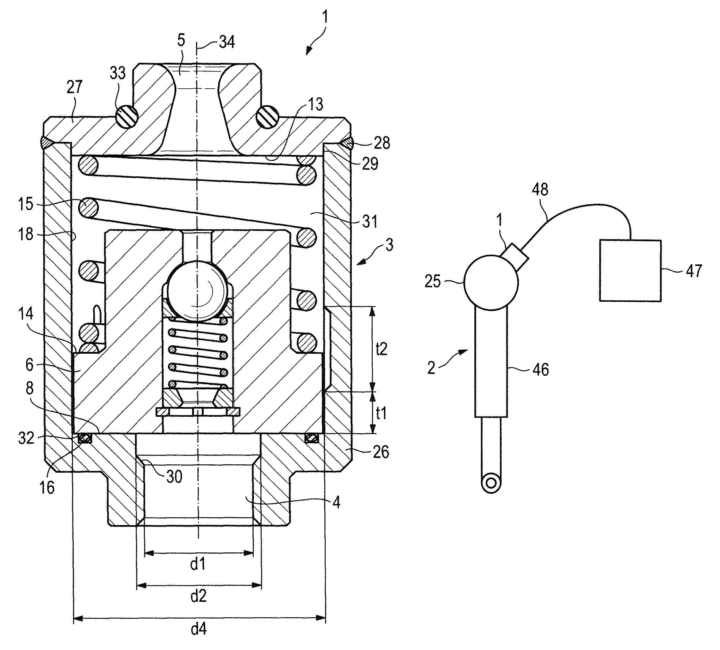
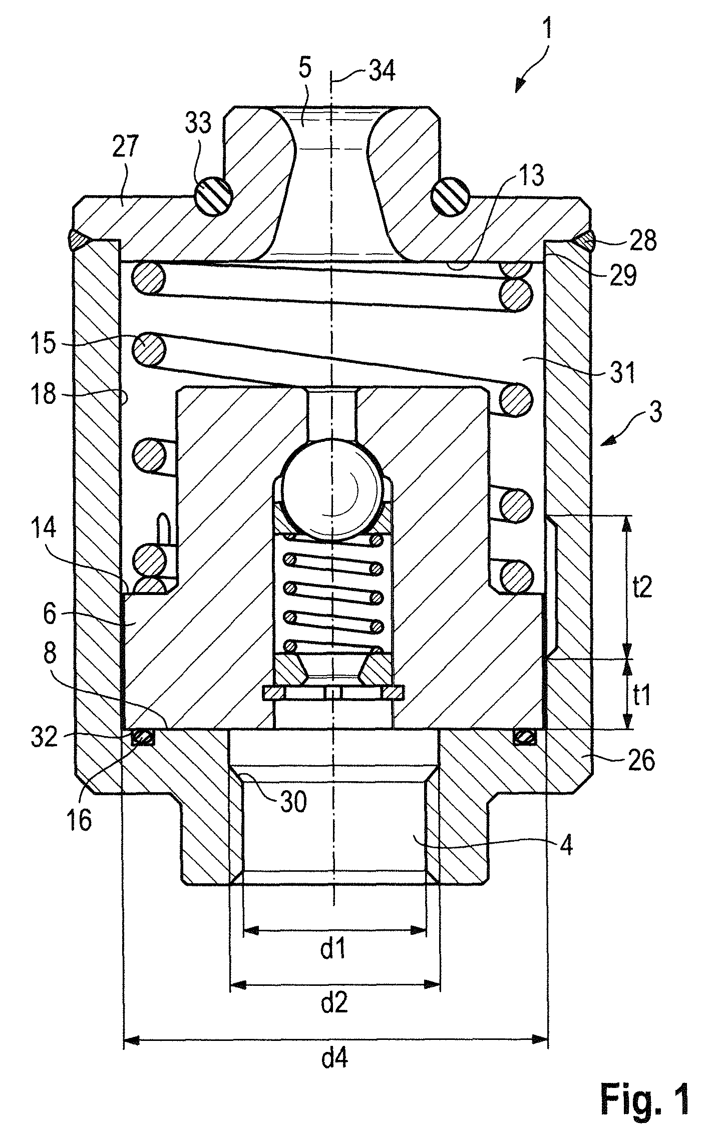
[0036]FIG. 1 illustrates a residual pressure holding valve 1 for a hydropneumatic suspension strut of a motor vehicle. The residual pressure holding valve 1 has a valve housing 3 in the shape of a hollow cylinder with an air inlet 4 and an air outlet 5. The valve housing 3 is composed, for example, of a bowl-shaped lower part 26 and a cover 27 that terminates the bowl-shaped lower part 26. The air inlet 4 is in the lower part 26, and the air outlet 5 is in the cover 27. The components 26, 27 are welded to one another in a gastight fashion at a seam 28. In alternative embodiments of the valve housing, the components 26, 27 can, for example, be screwed or adhesively bonded to one another. The cover 27 is guided centrally along an inner wall 18 of the valve housing 3 by means of a collar 29, for example. In other embodiments the valve housing 3, for example, can be constructed from more than two components. The air inlet 4 is a stepped bore in the form of a pneumatic quick-release coup...


PUM


Abstract

A residual pressure holding valve (1) for a hydropneumatic suspension strut (2) of a motor vehicle has a valve housing (3) with an air inlet (4) and an air outlet (5). A valve body (6) is arranged displaceably in the valve housing (3) and a valve element (7) is arranged displaceably in the valve body (6). Air pressure applied to the air inlet (4) can lift the valve body (6) off a valve body seat (8) of the valve housing (3) to allow air to flow past the valve body (6) to the air outlet (5). Air pressure applied to the air outlet (5) can lift the valve element (7) off a valve element seat (9) of the valve body (6) to allow air to flow past the valve element (7) to the air inlet (4).

Description

CROSS REFERENCE TO RELATED APPLICATION[0001]This application claims priority under 35 USC 119 to German Patent Application No 10 2010 020 524.9 filed on May 14, 2010, the entire disclosure of which is incorporated herein by reference.BACKGROUND OF THE INVENTION[0002]1. Field of the Invention[0003]The invention relates to a residual pressure holding valve and to a suspension strut with such a residual pressure holding valve, in particular for a motor vehicle.[0004]2. Description of the Related Art[0005]The invention can be applied to any vehicle, but will explained in detail, along with the problems on which it is based, with respect to a passenger motor vehicle.[0006]Hydropneumatic suspension systems in motor vehicles permit the spring system to be adapted in a convenient, fast and versatile fashion to conditions of the roadway, the payload of the motor vehicle and / or the driving properties of the chassis of the motor vehicle desired by a vehicle driver. The spring effect of such a ...

Claims


Application Information

Patent Timeline
Patent Type & Authority Patents(United States)
IPC IPC(8): F16F9/56
CPCF16K17/18B60G17/0528F16K17/196
Inventor GERMANO, FRANCESCOLANG, STEFFENBLATTNER, CLAUSSPRENGEL, THOMAS
Owner DR ING H C F PORSCHE AG
Why Eureka
Try Eureka