
Device, machine and method for applying glue capable of flowing

Inactive Publication Date: 2006-12-07
ROBATECH
View PDF2 Cites 8 Cited by
  • Summary
  • Abstract
  • Description
  • Claims
  • Application Information

AI Technical Summary

Benefits of technology

[0009] The present invention includes a glue applying device, a machine incorporating the glue application device, and a method for using the device and machine in combination to reproducibly apply at least two glue beads running parallel to each other. In addition, a corresponding method is to be provided. It is a particularly important feature of the invention that it is possible to precisely adjust the distance between glue strips to distance of less than 10 mm.
[0011] In a preferred embodiment, the pinion gear is controlled and driven by a manual means, (e.g., a crank handle), or by an engine or motor. In this embodiment, the glue applying device is mounted in combination with a machine of which the pinion gear and drive means comprise a part. It is a feature of the present embodiment that a continuous (or step-less) drive means, like the pinion and toothed gear mechanism, provide very precise adjustability of the distance between adjacent glue line of between 0 and 10 mm. The invention is particularly suitable for the application of glue with variable strip distance. The distance can be adjusted very easily and exactly. Further advantages of the invention can be derived from the figures and the following description.

Problems solved by technology

One of the problems in the field lies in the fact that a machine for applying the side glue should be applicable as flexibly as possible, so that it can be adapted fast and problem-free with respective to a specific printing order.
This approach is particularly complex with PUR-based adhesives, since PUR hardens relatively quickly if exposed to air.
In addition, the re-configuring of such a machine can be relatively complex.
The conventionally working machines are also problematic if glue beads with a distance of less than 10 mm have to be applied.

Method used


Image

  • Device, machine and method for applying glue capable of flowing
  • Device, machine and method for applying glue capable of flowing
  • Device, machine and method for applying glue capable of flowing

Examples


Embodiment Construction

[0021] Referring now to the drawings, the details of preferred embodiments of the present invention are graphically and schematically illustrated. Like elements in the drawings are represented by the like numbers, and any similar elements are represented by like numbers with a different lower case letter suffix.

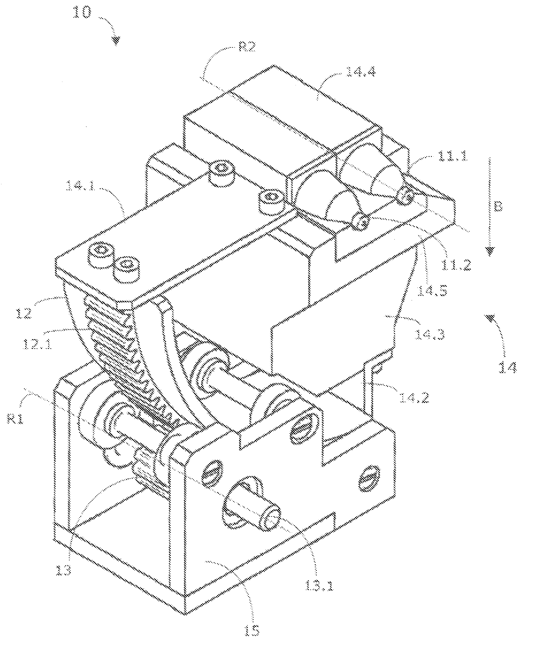
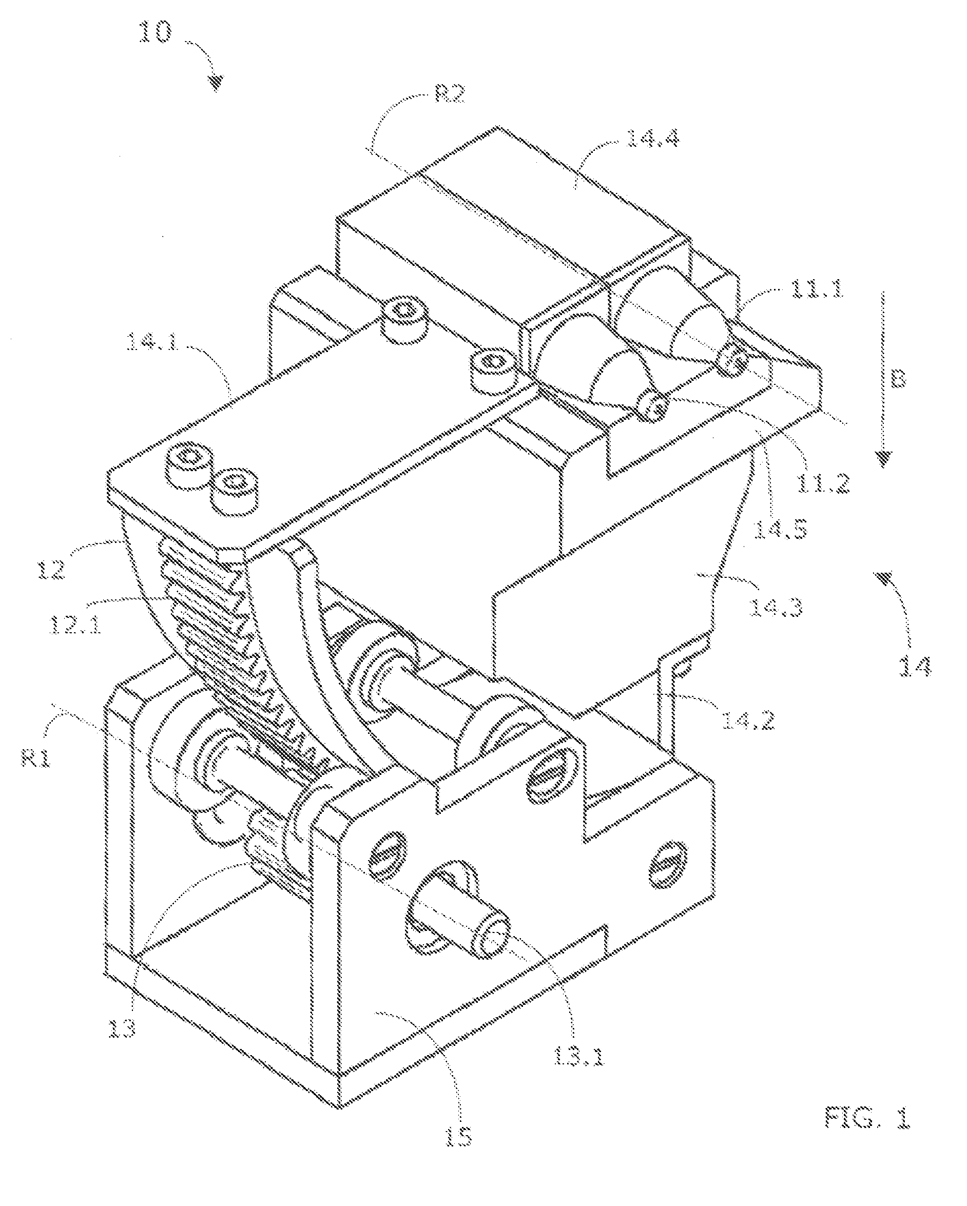
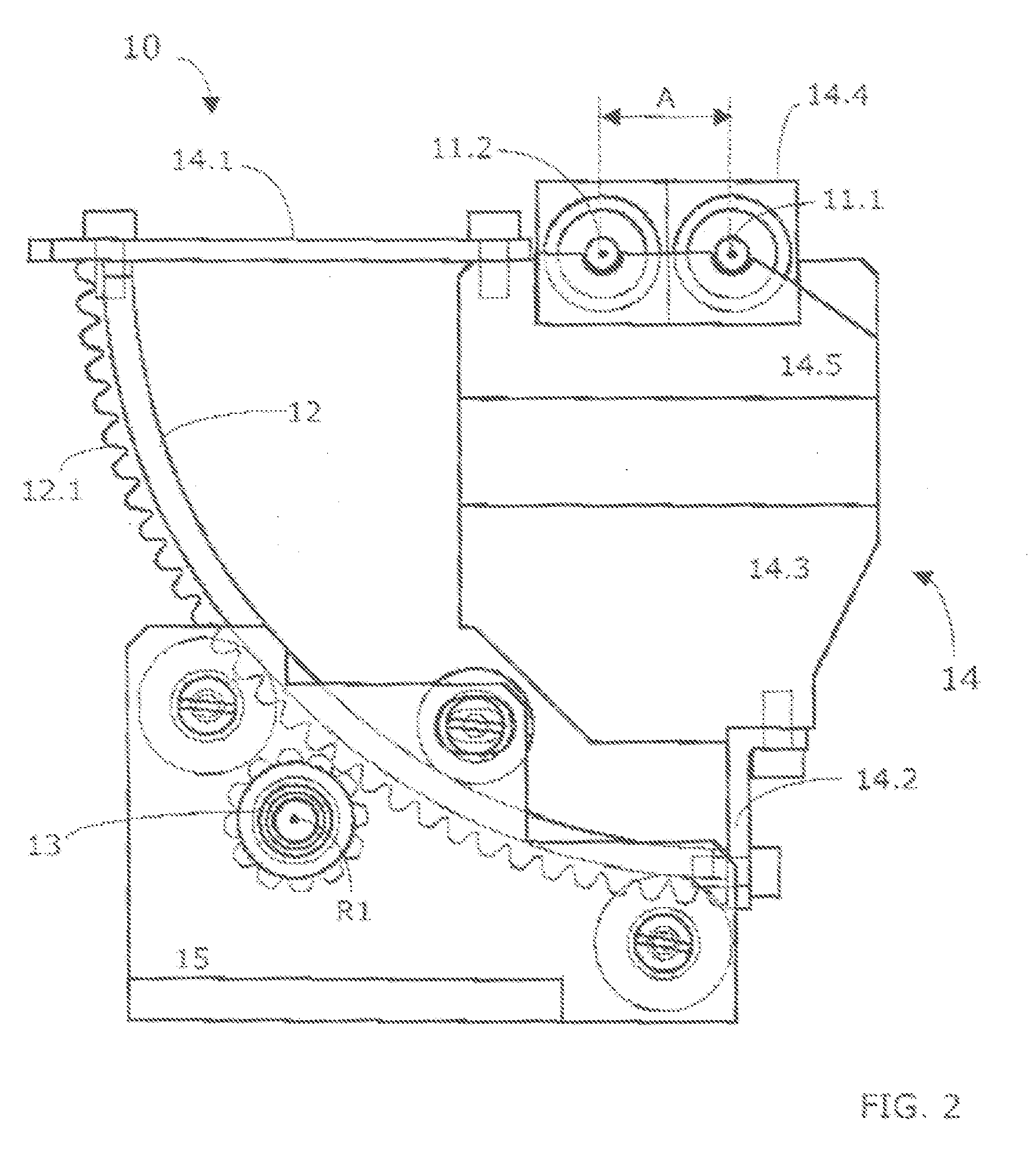
[0022] The present invention concerns a machine comprising at least one glue application device for use in the application on a surface of two or more glue paths running parallel to each other. These paths are also called glue beads. In FIGS. 1 and 2, a preferred glue application device 10 according to invention is shown. The glue application device 10 is part of a machine 40 (see FIG. 7). The glue device 10 serves in the example shown for applying fluid glue in two essentially parallel running strips 23 or 24 on an object or surface 20, see FIGS. 3A and 3B. In accordance with invention the device 10 comprises two nozzles 11.1, 11.2 and a suspension member 14 to which the tw...


PUM

PropertyMeasurementUnit
Diameteraaaaaaaaaa
Radiusaaaaaaaaaa
Distanceaaaaaaaaaa

Abstract

A machine and method is provided for applying a fluent adhesive or glue to a surface in two or more parallel strips at a adjustable distance apart. The machine has a plurality of glue nozzles mounted on a radius of a suspension device, which has an arcuate shape and is pivotable about the axis of the radius of the arc. The parallel adhesive strips are accomplished by applying the glue to the surface while moving the surface linearly past the nozzles. Adjustment of the distance apart is accomplished by rotation of the arc of the suspension device about its pivot axis by a swivelling means, which alters the angular distance between the nozzles relative to the direction of movement.

Description

[0001] The present application claims the benefit of prior filed European Patent Organization Application, serial number EP 05 011979.1 filed 3 Jun. 2005, to which the present application is a regular U.S. national application. FIELD OF THE INVENTION [0002] The present invention is in the field of machines, devices and methods for the application of adhesives in at least two parallel tracks. BACKGROUND OF THE INVENTION [0003] When processing printed products, but also in other fields, there is a need to apply two or more parallel glue breads, in order to be able to glue on for example a book cover or the like. [0004] Within the printing field one talks about so-called side coating, which consist typically of two glue beads running parallel to each other on each side of an already bound book block. These glue beads run along the bound back on the front and back side of the book block. After application of the side glue the back of the book, or another cover is then put and pressed ar...

Claims


Application Information

Patent Timeline
IPC IPC(8): B32B37/02B05C5/02B05B15/68
CPCB05B15/08B42C9/0006B05C5/0208B05C5/02B05B15/68
Inventor BUDA, ANDREASFELIX, HANSPETER
Owner ROBATECH
Learn More