
Tension leg and method for transport, installation and removal of tension legs pipelines and slender bodies

a technology of tension leg and pipeline, which is applied in the direction of floating buildings, bulkheads/piles, and fluid removal. it can solve the problems of inability to achieve desirable, increased displacement of platforms, and increased tendons, so as to reduce the inherent buoyancy of the tendon, eliminate or significantly reduce the effect of external stresses generating buckling loads

Inactive Publication Date: 2003-07-03
ANCHOR CONTRACTING
View PDF0 Cites 10 Cited by
  • Summary
  • Abstract
  • Description
  • Claims
  • Application Information

AI Technical Summary

Benefits of technology

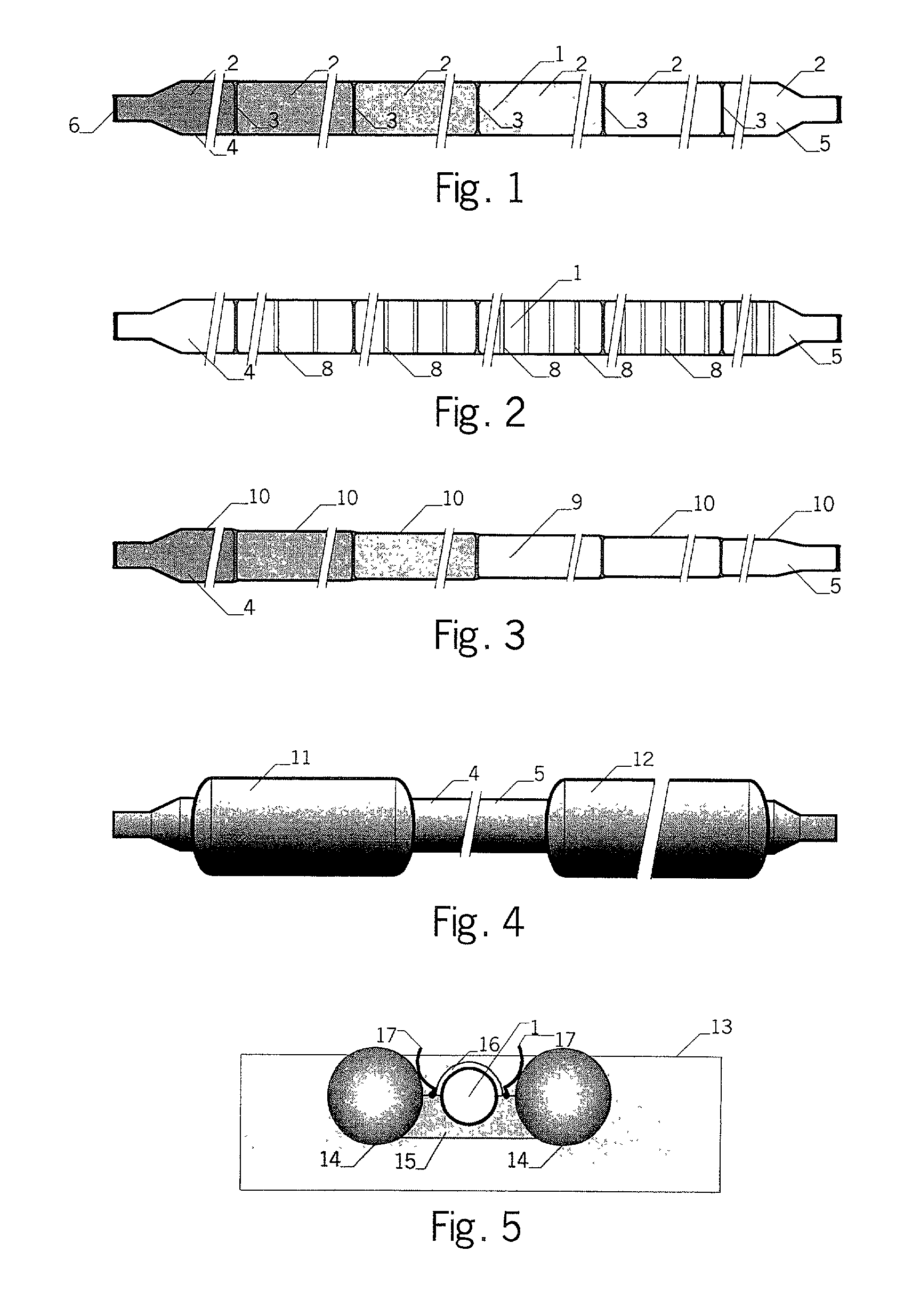
[0013] In accordance with the present invention the tendon is designed and made, in traditional fashion, of hollow cylindrical sections such as pipes that are connected into a continuous string. However, the interior of the string is divided into one or several compartments. The optimum number of compartments depends on water depth at installation area, typically 6 to 10. Before installation of the tendon each of the compartments is pressurized by gas, e.g. nitrogen or dried air, to a pressure that is close or equal to ambient water pressure at the depth where the compartment will be found after completed installation. Hence, the undesirable external stresses generating buckling loads are eliminated or significantly reduced during the time when the tendon is in use. This opens for the possibility to increase diameter, thus increase the inherent buoyancy of the tendon without the need of larger wall thickness, as it would be required if the traditional design would be applied. Therefore, the designer can optimize the diameter in order build-in desirable buoyancy for transport, installation, operation and finally removal. At the same time pipes of standard dimensions can be used and material saving is achieved, typically 30% weight reduction compared to standard design of tendons for a deepwater platform (i.e. platform at more than 3.000 ft water depth).
[0014] The tendon can be designed with uniform diameter over its entire length in order to eliminate locations exposed to fatigue stresses. In such a case the tendon upon completion of pressurization would have stepwise increasing net buoyancy when floating in surface because of decreasing weight of pressurized gas in the compartments, the bottom compartments being the heaviest thus least buoyant. Since the transport and installation method requires uniformly distributed net buoyancy the excessive buoyancy is counterweighted by ballast added.
[0015] The tendon can also be designed with stepped diameter so that the above-explained need for ballast is eliminated. In such a case attention is paid to design of details of the transitions so that the fatigue loads are eliminated or significantly reduced.

Problems solved by technology

Hence, when installed the tubular pipes / tendon are exposed to outer hydrostatic pressure that is an disadvantageous buckling-type loading calling for increasing the wall thickness to diameter ratio, i.e. increasing wall thickness and decreasing diameter.
The final consequence is that the platform's displacement must be increased that again causes larger loads on the tendons etc.
In deeper waters it is not feasible to achieve a desirable or optimum design, namely neutrally or positively buoyant tendon.
Such transitions attract stresses causing material fatigue.
Uniform diameter tendon eliminating the fatigue stresses on the penalty of small diameter thus large loads on the platform with the associated negative consequences.
This is an expensive solution due to expensive vessel and connectors.
Two major drawbacks are associated with such methods: (a) When towed in waves, the tendon is exposed to fatigue stresses; and (b) Large risk is associated with the use of external temporary elements, as experienced in practice.
Another disadvantage is associated with these methods that is non-reversibility of some of operations.
Upon negative experience from practical applications the industry is hesitant for further use of these methods.
Also these methods are associated with disadvantages.
The latter is characterized by demanding control, large loads involved and lack of facility to bring the body to surface in case of contingency or for planned operations such as connection with other sections or preparation for installation.

Method used


Image

  • Tension leg and method for transport, installation and removal of tension legs pipelines and slender bodies
  • Tension leg and method for transport, installation and removal of tension legs pipelines and slender bodies
  • Tension leg and method for transport, installation and removal of tension legs pipelines and slender bodies

Examples


Embodiment Construction

[0052] FIG. 1 shows schematics of a tendon 1 with uniform diameter that is divided by inner bulkheads 3 into compartments 2. The compartments 2 are pressurized by gas to nearly ambient pressure at the operation depth where the lower compartment 4 has the largest pressure and the upper compartment 5 has the lowest pressure, often equal to atmospheric pressure. Shading of different density indicates the pressure level in the individual compartments 2, 4 and 5. Each of the inner bulkheads 3, is outfitted for pressurization by gas or for both pressurization by liquid (for pressure testing) and for final pressurization by gas. In the former case the outfitting includes a valve and a backup valve on a pipe through the bulkhead as shown in FIG. 24.

[0053] FIG. 24 shows an arrangement of a bulkhead 3 separating adjacent compartments 2 and with outfitting for final pressurization consisting of a pipe 56 with valves 57 and 58 (one of these as backup). Upon completion of pressurization the valv...


PUM


Abstract

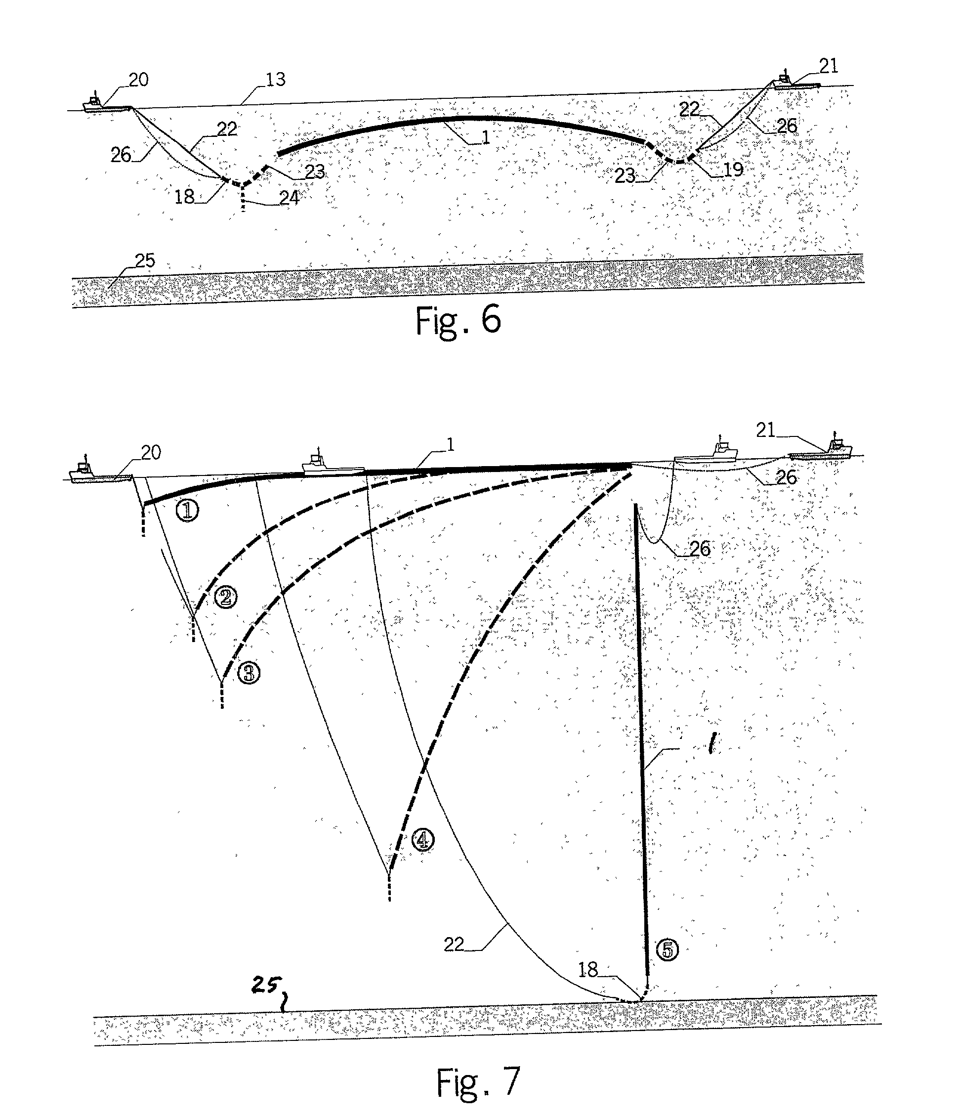
The present invention provides a tendon divided into compartment enclosing therein pressurized gas. The invention also relates to a method for transporting a fluid containing tubular body or assembly of bodies above a sea / river bed floor and within a body of water. In addition the invention comprises a method of installing and removing an internal pressurized tendon or assembly of tendons in a vertical position in a body of water.

Description

1. FIELD OF THE INVENTION[0001] The present invention relates to the design of tension legs, i.e. tendons for Tension Leg Platforms (TLP) and method for transport and installation and removal / replacement of tendons and similar slender bodies in a body of water.2. DESCRIPTION OF THE PRIOR ART[0002] There are two main types of tendons:[0003] Rods made of composite or fiber materials, and[0004] hollow circular pipes welded into sections where the design seeks to utilize the buoyancy as much as possible to reduce submerged weight of the tendon in order to lessen the size of the platform that carries the weight of the tendons.[0005] A major feature of the latter concept is that air at atmospheric pressure is present in the interior of the pipes in a tendon. Hence, when installed the tubular pipes / tendon are exposed to outer hydrostatic pressure that is an disadvantageous buckling-type loading calling for increasing the wall thickness to diameter ratio, i.e. increasing wall thickness and ...

Claims


Application Information

Patent Timeline
IPC IPC(8): B63B21/50
CPCB63B21/502
Inventor KARAL, KARELHOGMOE, JORGENRAMSLI, SIGURDLASSEN-URDAHL, JOHAN
Owner ANCHOR CONTRACTING
Learn More