
Multi-mesh gear system

a gear system and multi-mesh technology, applied in the direction of gearing, gearing elements, hoisting equipment, etc., can solve the problems of reducing the effective torque capacity of the gear mesh, affecting the quality of the gear, so as to achieve the effect of increasing the sound power

Inactive Publication Date: 2003-06-12
AXICON TECH
View PDF0 Cites 20 Cited by
  • Summary
  • Abstract
  • Description
  • Claims
  • Application Information

AI Technical Summary

Benefits of technology

[0014] In general, in one presently preferred embodiment broadly in accordance with the invention, a multi-mesh gear system is provided that is optimized to minimize the self-excited component of dynamic load across substantially all operating loads without a significant increase in manufacturing complexity or cost. This should have the effect of reducing noise and improving load-life performance. Generally, in one preferred embodiment broadly contemplated by the invention, a multi-mesh gear system that utilizes substantially the same contact ratio for all meshes within the multi-mesh gear system in combination with the use of a mesh stiffness variation reducing (MSVR) type of gear tooth modification is disclosed herein.
[0016] Differential Crowning, for the purposes of this disclosure, can be defined as the introduction of different forms and amounts of lead crowning at different positions along the height of the gear tooth to reduce the variation in mesh stiffness that occurs as the number of tooth pairs in contact changes during a mesh cycle. Differential Crowning is effective at substantially all loads because it changes the tooth stiffness elastically rather than by introducing an initial separation of the teeth.

Problems solved by technology

In addition to serving as the primary excitation for gear noise, this dynamic increment serves to reduce the effective torque capacity of the gear mesh.
At all other loads, the initial separation will be sub-optimal and in fact typically degrades performance.
There are, however, two major drawbacks to the disclosed solution.
One, the manufacturing complexity and cost would significantly increase by requiring the manufacture of different profile modifications on the opposing tooth flanks of the planet gears.
Two, the profile modifications specified in the referenced patent disclosure are limited to conventional modifications, such as tip and / or root relief, which utilize initial separation, and as a consequence, minimize mesh stiffness variation at one specific load only.

Method used


Image

  • Multi-mesh gear system
  • Multi-mesh gear system
  • Multi-mesh gear system

Examples


Embodiment Construction

[0027] It should be clear to those of ordinary skill in the art that the multi-mesh gear system embodying the disclosed inventions utilizes the standard parts of an epicyclic gear system and that standard gear action applies. As shown in FIG. 1, teeth 1 on sun gear 2 and teeth 3 on the planet pinion gears 4 are in mesh. Teeth 3 on the planet pinion gears 4 are in mesh with the teeth 6 on ring gear 7. The MSVR modifications discussed herein may be applied, although not shown on FIG. 1, to any one or all of the teeth 1,3,6 on any one or all of the gears 2,4,7 in accord with the principles of the invention.

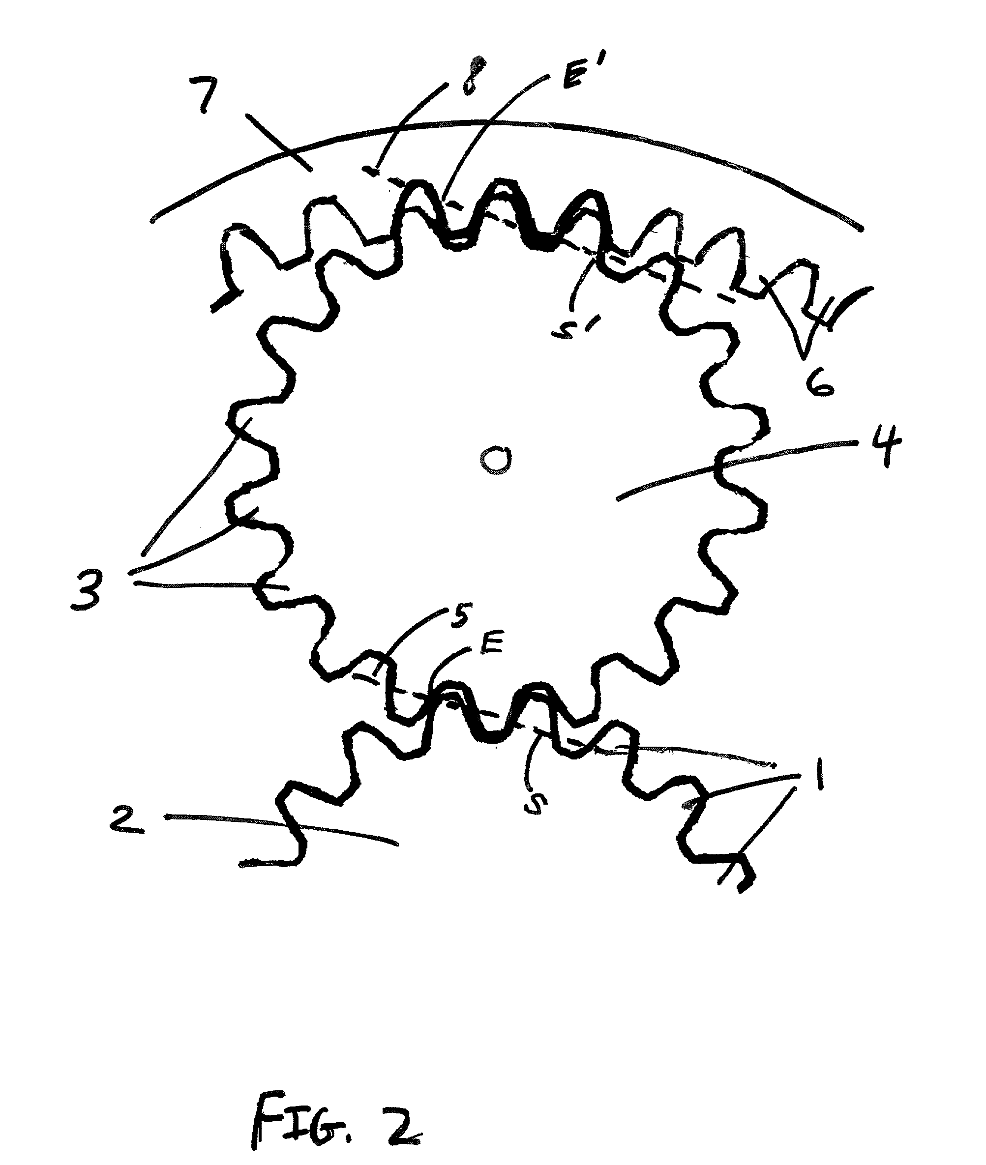
[0028] As shown in FIG. 2, teeth 1 on sun gear 2 and teeth 3 on planet pinion gear 4 make contact along a pressure line 5 that contains the path of contact extending from Point S and ending at Point E. Teeth 3 on the planet pinion gear 4 also make contact with teeth 6 on ring gear 7 along a pressure line 8 that contains the path of contact extending from Point S' and ending at Point ...


PUM


Abstract

Disclosed herein is a multi-mesh gear system, such as an epicyclic gear system, in which (a) optimal performance is not load-specific and (b) the same profile modifications can be applied on both flanks of the common gear. This is accomplished through a novel combination of a constant system contact ratio and gearing having mesh stiffness variation reducing, or MSVR, modifications. An MSVR modification, such as Differential Crowning, will minimize the self-excited component of dynamic load for gear meshes across different operating loads, resulting in an optimized gearset. The specification of a substantially constant contact ratio for the multi-mesh gear system allows the same MSVR modification to be used on both tooth flanks of the common gear, reducing the cost and complexity of manufacture.

Description

I. BACKGROUND OF THE INVENTION[0001] A. Field of the Invention[0002] The invention disclosed herein relates generally to a multi-mesh gear system as well as to the design thereof. Generally, at least one presently preferred embodiment of the invention broadly relates to a multi-mesh gear system having design characteristics that reduce the self-excited component of dynamic load. It is also disclosed herein how to do so without significantly increasing the cost or complexity of manufacture. As a consequence of the reduced dynamic loading, the presently preferred multi-mesh gear systems disclosed herein generally have reduced noise and increased torque capacity or load-life performance when compared to conventional multi-mesh gear systems. Generally and broadly speaking, presently preferred gear systems and a presently preferred method of designing said gear systems that achieve desirable performance and cost characteristics are disclosed.[0003] B. Description of the Prior Art[0004] A...

Claims


Application Information

Patent Timeline
IPC IPC(8): F16H1/28F16H55/08
CPCF16H55/0886F16H1/28
Inventor ALLEN, MARK ANDERSONWYETH, MARK T.KIM, HANJOON ALEX
Owner AXICON TECH
Learn More