
Double-drive stirling travelling wave refrigerating device

A refrigerator and dual-drive technology, applied in refrigerators, gas cycle refrigerators, refrigeration and liquefaction, etc., can solve the problems that are difficult to be used in compact occasions, affect the energy utilization efficiency of the device, and have low thermoacoustic conversion efficiency. , to achieve the effects of suppressing standing wave components, small loss, and simple structure

Inactive Publication Date: 2012-03-07
WUHAN INSTITUTE OF TECHNOLOGY
View PDF3 Cites 0 Cited by
  • Summary
  • Abstract
  • Description
  • Claims
  • Application Information

AI Technical Summary

Problems solved by technology

For example, the US patent US4722201 "Acoustic Cooling Engine" proposes that under the drive of a single sound source, the cooling capacity is generated by the thermoacoustic stack arranged in the resonant tube; the Japanese patent JP8014679 "Thermoacoustic Freezing Cycle and Cooling Device" describes a quarter-wavelength Single refrigeration system; Japanese patent JP2000337724 "Acoustic Refrigeration System" also introduces a single refrigeration system driven by a single sound source; Chinese patent CN1657842A "multi-sonic refrigerator" can achieve the purpose of multi-point refrigeration, but it is still a single sound source (speaker) Driven Standing Wave Refrigeration System
The disadvantages of these systems are that the cooling capacity is relatively low, and it is difficult to be used in compact occasions; the second is that the thermoacoustic conversion efficiency is low, which affects the energy utilization efficiency of the device

Method used


Image

  • Double-drive stirling travelling wave refrigerating device
  • Double-drive stirling travelling wave refrigerating device

Examples


Embodiment Construction

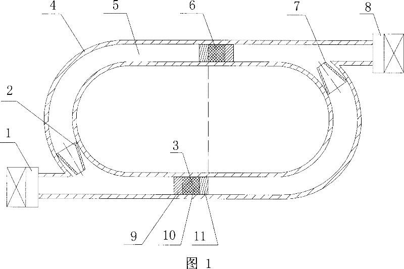
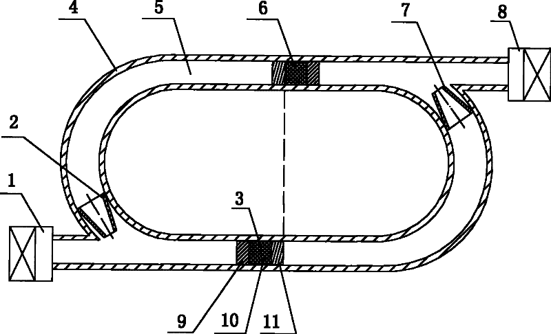
[0016] like figure 1 As shown, the dual-drive Stirling traveling wave refrigerator includes a first exciter 1, a first anti-traveling wave suppressor 2, a first thermoacoustic cooling element 3, an annular channel housing 4, and a second thermoacoustic cooling element 6 , the second anti-traveling wave suppressor 7, the second exciter 8; the annular channel housing 4 is an annular traveling wave transmission channel 5, the length of the annular traveling wave transmission channel 5 is one wavelength, and the annular channel housing 4 is symmetrical A first port and a second port are provided, and the first port and the second port communicate with the annular traveling wave transmission channel 5 respectively; the first exciter 1 is arranged at the first port on the annular channel housing 4 (the first vibrator 1 is fixedly connected to the annular channel housing 4), the output end of the first vibrator 1 faces the first port, and the second vibrator 8 is arranged on the seco...


PUM


Abstract

The invention relates to a traveling-wave thermo-acoustic heat engine (refrigerator). A double-drive stirling traveling-wave refrigerator is characterized by including a first vibration exciter (1), a first thermo-acoustic refrigeration element (3), a ring-shaped channel housing (4), a second thermo-acoustic refrigeration element (6) and a second vibration exciter (8), wherein a ring-shaped traveling-wave transmitting passage (5) is arranged inside the ring-shaped channel housing (4), the first vibration exciter (1) is arranged at the first port of the ring-shaped channel housing (4), the second vibration exciter (8) is disposed at the second port of the ring-shaped channel housing (4), the first thermo-acoustic refrigeration element (3) and the second thermo-acoustic refrigeration element (6) are respectively distributed inside the ring-shaped traveling-wave transmitting passage (5), one end close to the first vibration exciter (1) of the first thermo-acoustic refrigeration element (3) is a hot end heat exchanger (9), and one end close to the second vibration exciter of the second thermo-acoustic refrigeration element (6) is a hot end heat exchanger. The double-drive stirling traveling-wave refrigerator has the advantages of simple structure and high efficiency, which can realize double objects cooling and single object cooling.

Description

technical field [0001] The invention belongs to the technical field of refrigeration and low temperature engineering, and in particular relates to a traveling wave thermoacoustic heat engine (refrigerator). Background technique [0002] Thermoacoustic refrigeration is a refrigeration technology that uses the thermoacoustic effect to pump heat. Under certain conditions, the phenomenon of mutual conversion of heat energy and sound energy is called thermoacoustic effect. It refers to the time-averaged energy effect between the acoustic oscillation of the compressible fluid and the solid medium due to the thermal interaction. According to the direction of energy conversion, thermoacoustic effects can be divided into two categories: one is sound generated by heat, that is, thermally driven acoustic oscillation; the other is heat generated by sound, that is, heat pumping or cooling driven by sound. The thermoacoustic effect can be generated and acted in a standing wave sound fie...

Claims


Application Information

Patent Timeline
Patent Type & Authority Patents(China)
IPC IPC(8): F25B9/14
CPCF25B2309/1404F25B2309/1405
Inventor 吴锋李端勇丁国忠阚绪献伍坤
Owner WUHAN INSTITUTE OF TECHNOLOGY
Learn More