Device for generating a clock signal

a clock signal and device technology, applied in the direction of generating/distributing signals, instruments, pulse techniques, etc., can solve the problems of many functional limitations of the device, the device cannot make it possible to deliver an output clock signal, and the device described, so as to ensure the function of the generating device according to the invention

Active Publication Date: 2003-04-10
NXP BV
View PDF3 Cites 0 Cited by
  • Summary
  • Abstract
  • Description
  • Claims
  • Application Information

AI Technical Summary

Benefits of technology

[0010] The oscillator has the characteristic of functioning according to two distinct modes: in the forced mode when said first clock signal is actually present, in the free mode when said first clock signal is stopped. Said first clock signal corresponds in particular to a clock signal delivered by a microprocessor, possibly after frequency division by a factor of 1, 2, 4 or 8. The automatic and immediate switching from the forced mode to the free mode, as soon as said first clock signal stops, makes it possible to generate an output clock signal without discontinuity. Thus the circuits of the smart card receiving the output clock signal continue to be timed, and hence the processing operations currently being carried out on the smart card can continue.
[0015] Just as in the first embodiment, the oscillator has the characteristic of functioning according to two distinct modes: in a forced mode when said first clock signal is actually present, in a free mode when said first clock signal is stopped. Said first clock signal corresponds in particular to a clock signal delivered by a microprocessor, after any frequency division by a factor of 1, 2, 4 or 8. The automatic and immediate switching from the forced mode to the free mode, as soon as said first clock signal stops, makes it possible to generate an output clock signal without discontinuity. Thus the circuits in the smart card receiving the output clock signal continue to be timed, and the processing currently being carried out on the smart card can thus continue.
[0016] In addition, the use of the multiplexer has the advantage of generating, when said first clock signal delivered by the microprocessor is actually present, an output clock signal having a very slight shift in time compared with said first clock signal. Thus the processing circuits timed by the output clock signal and the processing circuits timed by said first clock signal are timed synchronously, which contributes to a greater reliability in processing and data exchange between the various processing circuits.
[0017] In addition to the fact that the control signal triggers the switching of the multiplexer, this control signal can advantageously serve to inform the smart card reader and the smart card that the input clock signal delivered by the microprocessor has stopped. Thus, under the action of this control signal, a procedure can be triggered for rapidly and rigorously finishing the processing being carried out on the smart card reader or on the smart card.
[0019] The functioning of the generating device according to the invention is guaranteed if the natural frequency of the oscillator is lower than the frequency of said first clock signal. This leads to an inexpensive solution since any good quality oscillator with a natural frequency lower than the frequency of said first clock signal can be chosen, even if its natural frequency undergoes variations over time.

Problems solved by technology

The device described in FIG. 1 has many functional limitations, in particular when said first clock signal 106 received by the generating device 101 stops.
Actually, such a generating device does not make it possible to deliver an output clock signal 102 when the input clock signal 106 delivered by the microprocessor 107 stops.
In addition, the processing operations being executed on the smart card are abruptly stopped, which may result in the storage of erroneous data in the memory elements of the smart card.

Method used


Image

  • Device for generating a clock signal
  • Device for generating a clock signal
  • Device for generating a clock signal

Examples


first embodiment

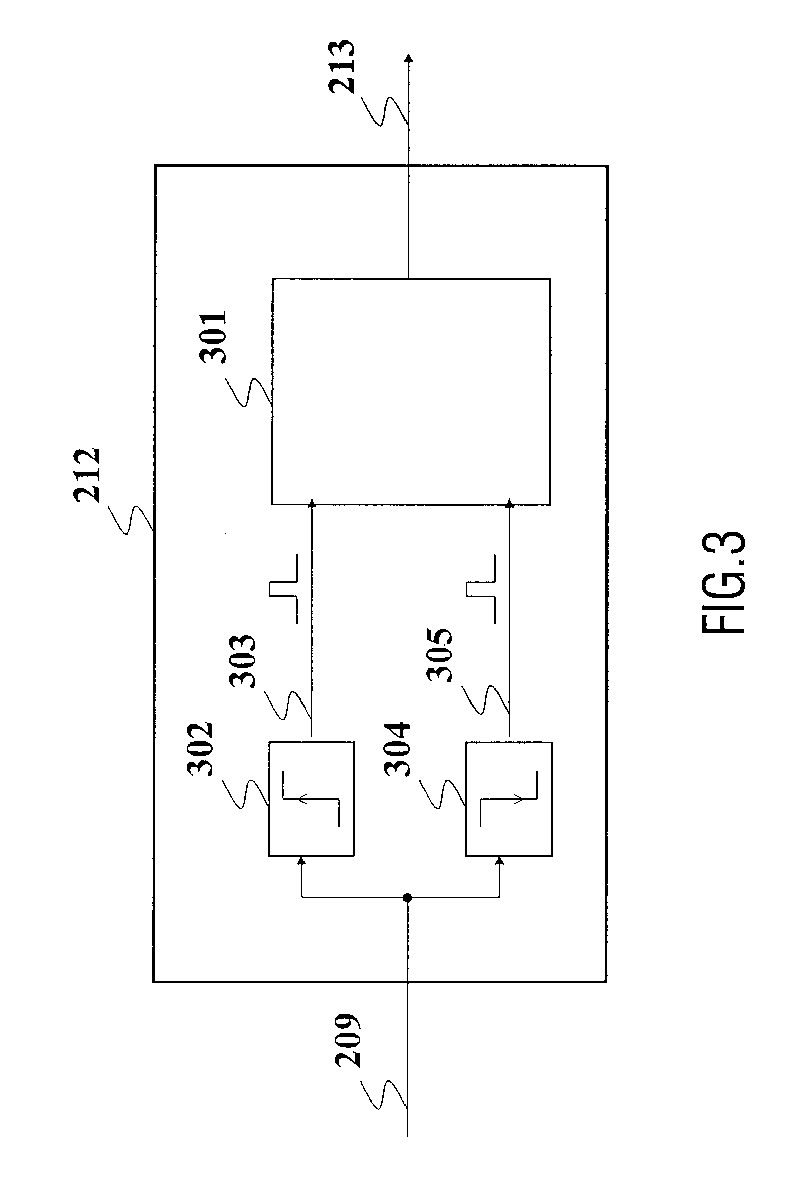
[0036] FIG. 3 is a functional representation of a device for generating a clock signal 213, according to the functional unit 212 described in FIG. 2. The functional unit 212 comprises an oscillator 301 generating said second clock signal 213 before any amplification by the amplification stage 211.

[0037] The oscillator 301 is characterized by the fact that it can function according to two different modes, that is, in a forced mode or in a free mode, according to the state of said first clock signal 209.

[0038] When said first clock signal 209 is actually present, that is, the signal 209 consists of a regular succession of rising and falling edges over time, the oscillator 301 functions in the forced mode. For this purpose, a rising edge detector 302 is provided, delivering an output pulse 303 to the oscillator 301 on each rising edge of the signal 209. Likewise, a falling edge detector 301 is provided delivering an output pulse 305 to the oscillator 301 on each falling edge of the sig...

second embodiment

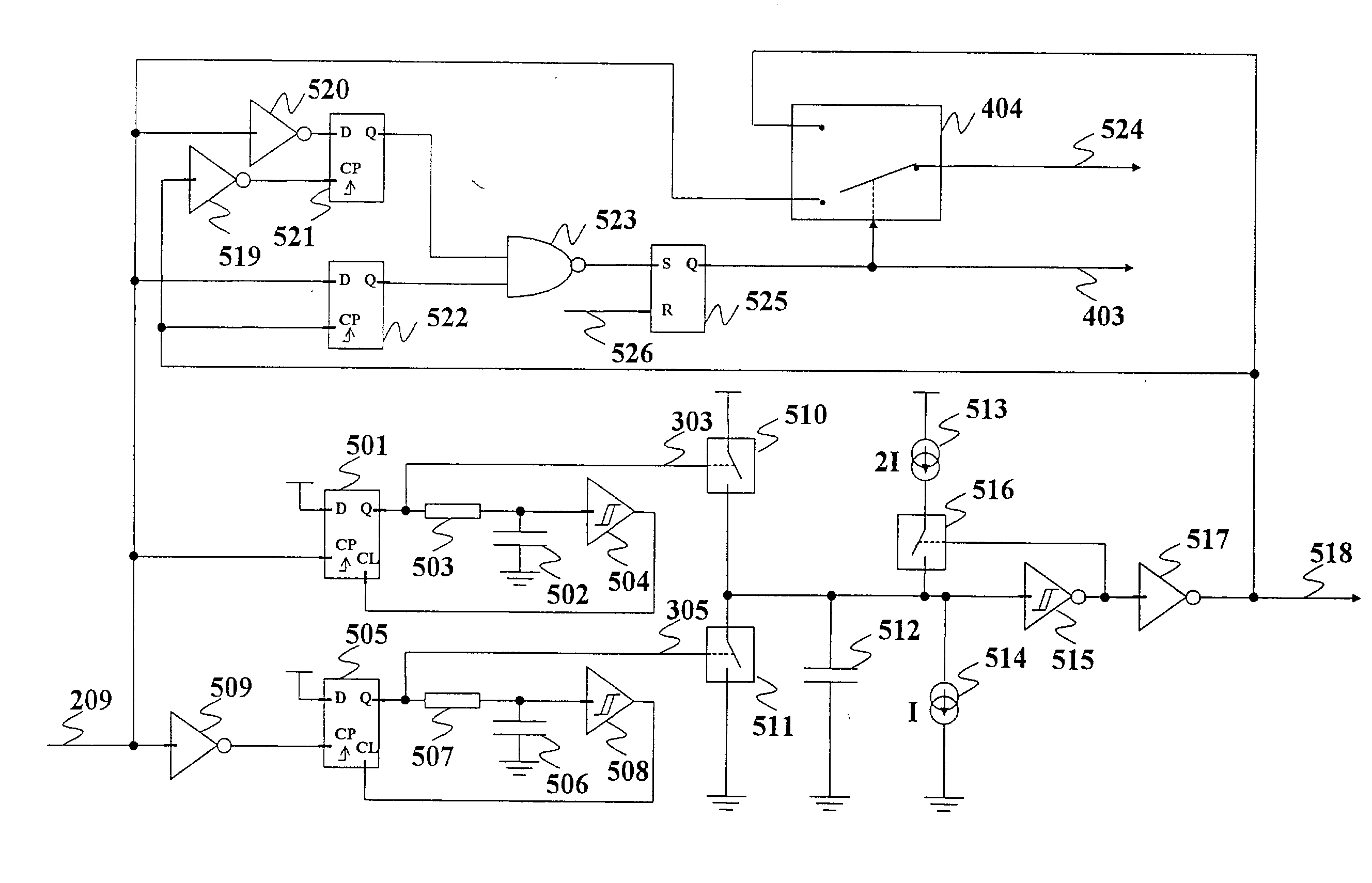
[0048] FIG. 4 is a functional representation of a device for generating a clock signal 213 according to the functional unit 212 described in FIG. 2.

[0049] This functional unit 212 is composed of the elements 301, 302 and 303 arranged in an identical fashion to FIG. 3, leading to the generation of the clock signal 401 by the oscillator 301. It also has a detector 402 for detecting the presence or absence of rising or falling edges in said first clock signal 209, in order to generate a control signal 403 with two logic levels. For this, the detector 402 performs a simultaneous analysis of the clock signals 209 and 401 which it receives at its inputs.

[0050] As seen previously, a rising edge of said first clock signal 209 triggers a rising edge in said second clock signal 401, and a falling edge of said first clock signal 209 triggers a falling edge in said second clock signal 401. Because of the inevitable processing delay in the circuits constituting the detectors 302 and 303, when th...


PUM


Abstract

A device 212 for generating an output clock signal 213 intended to time a digital processing circuit 204, said generating device receiving a first clock signal 209, characterized in that it comprises an oscillator generating a second clock signal constituting said output clock signal, said oscillator functioning in a forced mode under the control of the rising and falling edges of said first clock signal, said oscillator functioning in a free mode in the absence of rising or falling edges in said first clock signal, the natural frequency of said oscillator being lower than the frequency of said first clock signal. Use: clock signal generator

Description

[0001] The invention relates to a device for generating an output clock signal intended to time a digital processing circuit, said generating device receiving a first clock signal.[0002] The invention has many applications, in particular in smart card readers.TECHNOLOGICAL BACKGROUND TO THE INVENTION[0003] Smart cards include memory elements dedicated to the storage of information, such as information on the identity of an individual (for example the name, address etc.) or relating to administrative data for an individual (for example social security number, bank reference etc.). Smart cards also include processing circuits for performing operations on the data stored in said memory elements, conjointly with the data sent by a smart card reader. This is particularly the case in certain operations of the bank transaction type in which the smart card becomes a separate data processing unit. For the processing of data performed in parallel between the smart card reader and the smart ca...

Claims


Application Information

Patent Timeline
IPC IPC(8): G06F1/04G06K7/00G06F1/06H03K5/1532H03L7/00
CPCG06K7/0008G06F1/04
Inventor UGUEN, EMERIC
Owner NXP BV
Why Eureka
Try Eureka