
Fluorescence proximity assay

a proximity assay and fluorescence technology, applied in the field of binding assays, can solve the problems of adding additional, time-consuming, and often time-consuming steps to the assay, and achieve the effect of simple and straight forward operation

Inactive Publication Date: 2003-03-27
STANLEY MEDICAL RES HLDG
View PDF25 Cites 53 Cited by
  • Summary
  • Abstract
  • Description
  • Claims
  • Application Information

AI Technical Summary

Benefits of technology

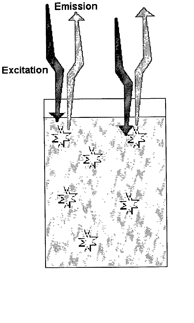
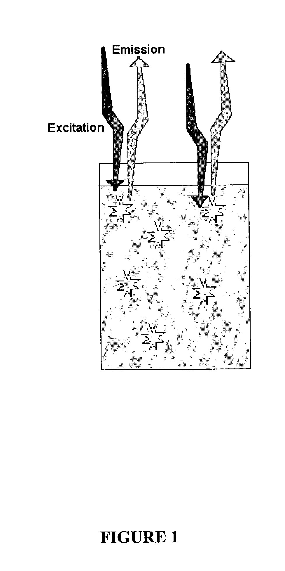
[0008] The present invention overcomes problems in the prior art and provides novel binding assays (referred to here as "fluorescent proximity assays" or FPAs) that are flexible, simple and easy to use. These assays are based, at least in part, on the discovery that when a fluorescent molecule or label is brought within close proximity of a gold or other metallic bead, the fluorescent signal intensity is not quenched as might be expected (see, for example, Duhachek et al., Anal Chem. 2000, 72:3709-3716; Enderlein, Biophys J. 2000, 78:2151-2158; Ruppin, J. Chem. Phys. 1982, 76:1681-1684; and Pineda et al., J. Chem. Phys. 1985, 83:5330-5337). Rather, the close proximity of the metallic bead to the fluorescent moiety actually enhances the fluorescent signal, resulting in a measured increase in the fluorescent signal intensity.
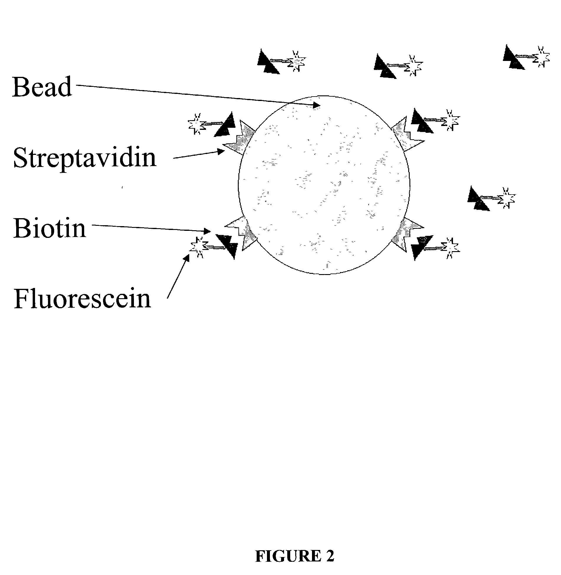
[0009] The invention therefore provides binding assays that are simple and straightforward to perform. In particular, the fluorescent proximity assays of this invention simply involve contacting a sample to a particle (preferably a gold or other metallic particle) that has a molecular probe bound or otherwise attached to its surface. The molecular probe may be, for example, an antibody molecule that specifically binds to a particular protein or antigen, or the molecular probe may be a nucleic acid molecule (e.g., an oligonucleotide probe) that specifically hybridizes to a complementary nucleic acid sequence. More generally, the molecular probe may comprise any probe or molecule that specifically binds to a "target molecule" to be detected in the sample.
[0012] The fluorescent proximity assays of this invention are simple and straight forward to perform, and offer particular advantages compared to other assays commonly used by persons skilled in the relevant art(s). For example, the molecular probes used in these assays may be attached or bound to a nanoscale or microscale bead, and need not be attached or bound to a solid surface or substrate. It is not necessary, therefore, to contact a sample to probes that have been immobilized, e.g., in a microarray, on the surface of a glass slide or plate, to the bottom of a microtiter well, or to a membrane, as one must do for traditional "solid-phase" or "multi-phase" binding assays that are commonly used. Instead, a fluorescent proximity assay of this invention can be performed in a single, homogeneous phase where the derivatized particles are suspended in a liquid medium, such as an aqueous solution or buffer.

Problems solved by technology

A significant problem with the implementation of such assays is the need to wash the sample and remove unbound ligand molecules.
This adds additional, often time consuming steps to the assays, complicating the procedure and reducing throughput.
However, these assays also suffer from technical drawbacks that may outweigh the advantage of eliminating a wash step.
Such assays are limited, however, by the optical clarity of the surface through which measurements are made.
This limitation results in a diminished signal per unit area.
It is therefore necessary to scan as much of the immobilization surface as possible, making the assay time consuming and reducing throughput for multiple samples.
Perhaps more significantly, the confocal imaging systems required to implement this type of assay are expensive and complicated.
These assays, however, are limited to the use of radio isotope labels, which require special handling procedures to protect users and the environment from radioactivity.
Such assays, however, are complicated by the requirement for two additional labels, and typically have only limited applications.

Method used


Image

  • Fluorescence proximity assay
  • Fluorescence proximity assay
  • Fluorescence proximity assay

Examples


Embodiment Construction

[0022] 6.1. Definitions

[0023] The terms used in this specification generally have their ordinary meanings in the art, within the context of this invention and in the specific context where each term is used. Certain terms are discussed below, or elsewhere in the specification, to provide additional guidance to the practitioner in describing the compositions and methods of the invention and how to make and use them. In addition, it is also noted that, within the context of this invention there may be employed conventional techniques of molecular biology, microbiology and recombinant DNA. Such techniques are well within the ordinary skill in the relevant art(s) and are fully explained in the literature. See, for example, Sambrook, Fitsch & Maniatis, Molecular Cloning: A Laboratory Manual, Second Edition (1989) Cold Spring Harbor Laboratory Press, Cold Spring Harbor, N.Y. (referred to herein as "Sambrook et al., 1989"); DNA Cloning: A Practical Approach, Volumes I and II (D. N. Glover ...


PUM

PropertyMeasurementUnit
Diameteraaaaaaaaaa
Diameteraaaaaaaaaa
Diameteraaaaaaaaaa

Abstract

The present invention provides binding assays, referred to here as fluorescence proximity assays or FPA. The inventions detect binding of target molecules in a sample to a molecular probe or probes that specifically bind or hybridize to those molecules. In particular, the molecular probes are immobilized to a bead or particle, such as colloidal gold, the reflects fluorescent energy from a fluorophore. The derivatized beads are contacted to a sample of fluorescently labeled target molecules, and binding of the target is indicated by an increase in the fluorescent signal. Kits are also provided that contain materials and reagents to performing a fluorescence proximity assay.

Description

1. PRIORITY INFORMATION[0001] Priority is claimed under 35 U.S.C. .sctn.119(e) to U.S. provisional patent application Serial No. 60 / 325,269 filed on Sep. 26, 2001, which is incorporated herein by reference in its entirety.2. FIELD OF THE INVENTION[0002] The present invention relates to binding assays for detecting the presence of particular molecules in a sample, such as particular polypeptides or particular nucleic acid sequences. In preferred embodiments, the invention relates to homogenous binding assays that use molecular probes attached to a particle or bead (e.g., colloidal gold), as opposed to probes that are immobilized on a membrane or other solid surface.3. BACKGROUND OF THE INVENTION[0003] High throughput specific binding assays provide an important tool in fields such as molecular biology and medical diagnostics. For example, nucleic acid molecules are typically detected in biological samples by hybridization to complementary nucleic acid probes. Generally, the probes ar...

Claims


Application Information

Patent Timeline
IPC IPC(8): C12Q1/68C12Q1/6818G01N33/543G01N33/553
CPCC12Q1/6818G01N33/54346G01N33/553C12Q2563/137C12Q2563/107
Inventor EVANS, DAVID MARK
Owner STANLEY MEDICAL RES HLDG
Learn More