
Apparatus for measuring in particular luminescent and/or fluorescent radiation

a technology for fluorescent radiation and measuring apparatus, applied in the field of apparatus for measuring in particular luminescent and/or fluorescent radiation, can solve the problems of failure to overcome, multi-label measuring instruments, and high-efficiency ligh

Inactive Publication Date: 2003-03-06
BERTHOLD TECH
View PDF9 Cites 46 Cited by
  • Summary
  • Abstract
  • Description
  • Claims
  • Application Information

AI Technical Summary

Benefits of technology

[0026] The common filter holder and its disposition in a horizontal plane above the specimen plane is the fundamental provision, including in the luminescence measuring device of the invention in the form of an individual measuring instrument, for a compact structure with a broad spectrum of applications, and it creates the structural prerequisites for simple expansion of the luminescence measuring device into a multipurpose measuring instrument.

Problems solved by technology

From European Patent Disclosure EP 0 803 724 A2, a multilabel measuring instrument is known which fails to overcome the above-discussed problems, primarily because the displaceable mirror block in it, designed for all kinds of measurements, prevents high-efficiency light passage for detecting weak luminescence signals.
This makes the results of measurement wrong, if a highly luminous specimen located next to a specimen of low luminosity is so bright that too high a value is measured at the low-luminosity specimen.
For reasons of optics, geometric size, the availability of lenses with special material and a certain index of refraction, compromises had to be made if a more or less common optical path was to be used, and the overall result of these compromises is low performance.

Method used


Image

  • Apparatus for measuring in particular luminescent and/or fluorescent radiation
  • Apparatus for measuring in particular luminescent and/or fluorescent radiation
  • Apparatus for measuring in particular luminescent and/or fluorescent radiation

Examples


Embodiment Construction

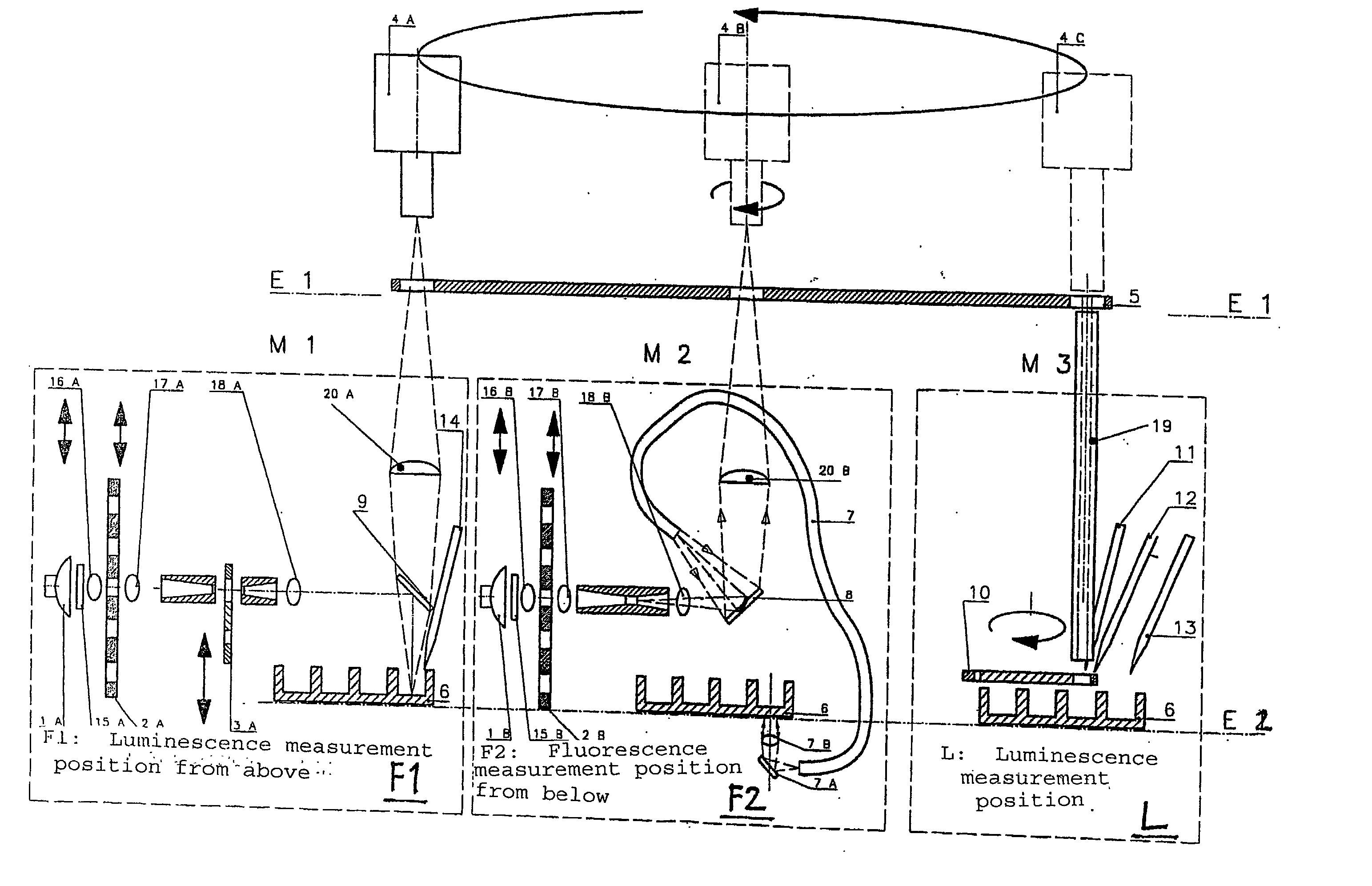
[0044] FIG. 1 is an overview of the components of the apparatus of the invention, taking as an example three measurement light paths, that is, a first measurement light path M1 with a first fluorescence measuring device F1 for a measuring fluorescence from above, a second measurement light path M2 with a second fluorescence measuring device F2 for measuring fluorescence from below, and a third measurement light path M3 with a luminescence measuring device L for measuring luminescence with or without filters. In all three measurements, the specimen holders, which are shown schematically as indentations in a microtiter plate 6, are located in a common specimen plane E2, which as a rule is embodied by a holder plate for the microtiter plates 6 which is displaceable horizontally by means of a motor system, not shown. Still other specimen carriers are also possible, such as membranes in which the specimens emit photons. The transport mechanism of the microtiter plate successively puts th...


PUM


Abstract

An apparatus for selected measurement of in particular luminescent and / or fluorescent radiation has a plurality of measurement light paths (M1, M2, M3), which each have their own measuring devices optimized for the particular measurement mode. As a common device, a filter holder (5) is used, in which the detector and each of the measuring devices have access to each of the openings of the filter holder, and each of these openings can be equipped with an emissions filter that is expedient for the particular measurement mode involved. The result is an especially compact arrangement of a multipurpose measuring instrument with measurement properties that is largely equivalent to the measurement properties of special individual measuring instruments and that is also suitable in particular as an individual instrument for special luminescence measurements, such as BRET measurements.

Description

[0001] Various producers of radiation measuring instruments using microtiter plates have changed over, because of decreasing budgets and a difficult cost structure for research, to instruments that can be used in multiple ways. The goal is to make a multipurpose instrument available to the customer for as many measuring methods as possible, in particular for measuring luminescence and fluorescence, so that it is unnecessary to procure a plurality of different individual instruments. Despite their higher price, compared to an instrument that is specialized for a particular measuring method, these multipurpose instruments are in strong demand. It is suggested that the customer by purchasing such a multipurpose instrument need not purchase individual instruments, especially since the price of the multipurpose instrument is less than the total price for dedicated instruments.[0002] At present, there are many different instruments, ranging from the "dual label" instrument for luminescenc...

Claims


Application Information

Patent Timeline
IPC IPC(8): G01N21/64G01N21/76
CPCG01N21/6452G01N21/76G01N2021/6471
Inventor PEUKERT, MICHAELKLAIBER, NORTBERTBREITKOPF, BERTHOLD
Owner BERTHOLD TECH
Learn More