High-energy beam irradiating desulfurization device

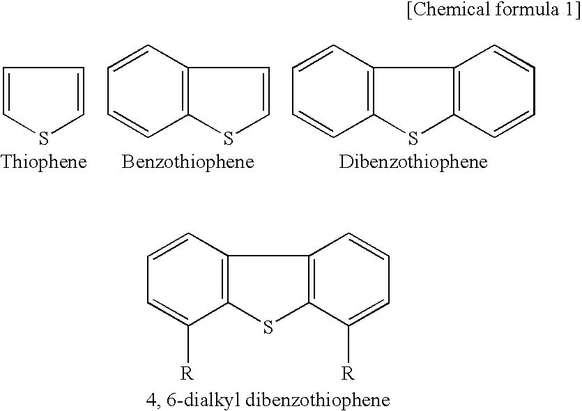
a technology of desulfurization device and high-energy beam, which is applied in the direction of energy-based chemical/physical/physical-chemical processes, chemical/physical/physical-chemical processes, chemical apparatus and processes, etc., can solve the problem of difficult to eliminate the same by conventional methods, difficulty in depth desulfurization of sulfur content capable of eliminating 4,6-dialkyl dibenzothiophene in light oil, and only proposed method of directing radioactive rays without actual use in practi

Inactive Publication Date: 2003-01-23
RIGAKU CORP
View PDF6 Cites 3 Cited by
  • Summary
  • Abstract
  • Description
  • Claims
  • Application Information

AI Technical Summary

Benefits of technology

[0016] The above-mentioned present invention is similar to the above-mentioned methods already proposed in that the desulfurization is executed by irradiating a high-energy beam. However, it is essentially different in terms of the technological concept of the desulfurization concerning all of the object of the invention, the configuration, and the operation effect. In particular, in the present invention, the depth desulfurization of the S content capable of eliminating the 4,6-dibenzothiophene in the light oil, which has conventionally been extremely difficult, can be carried out by irradiation of the high-energy beam. At the same time, a highly practical desulfurization device having the excellent efficiency can be provided.
[0041] By using these elimination methods in a combination, the desulfurization can be achieved by eliminating the produced metal sulfide utilizing a processing method according to the processing ability therein.

Problems solved by technology

However, as to the thiophene acid represented by the following formula, it is not easy to eliminate the same by the conventional methods.
In particular, the depth desulfurization of the sulfur (S) content capable of eliminating the 4,6-dialkyl dibenzothiophene in light oil has been extremely difficult.
However, the method of directing the radioactive ray has been only proposed without actual use in practice.
Furthermore, in the proposed method, the above-mentioned problem recognition in the depth desulfurization is not found.

Method used


Image

  • High-energy beam irradiating desulfurization device
  • High-energy beam irradiating desulfurization device
  • High-energy beam irradiating desulfurization device

Examples


Embodiment Construction

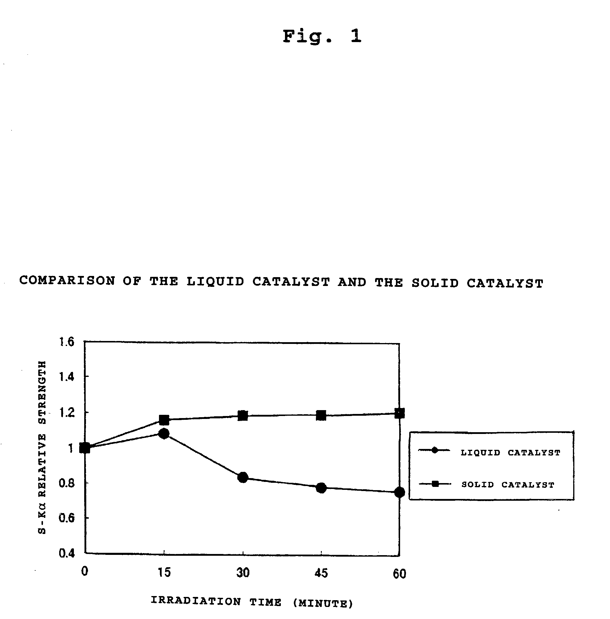
[0066] Desulfurization effect of the irradiation from above and the irradiation from below)

[0067] The desulfurization effect of the irradiation from above and the irradiation from below was evaluated using a specimen with a 50 ppm sulfur concentration.

[0068] (1) Experiment

[0069] As experiment specimen, a petroleum specimen with a 50 ppm sulfur concentration was prepared in a beaker with a liquid catalyst (silver nitrate solution catalyst) added.

[0070] As to the X ray irradiation condition, an Rh tube was used in a 20 kV-70mA condition with the silver absorption end wavelength cut. As to the irradiation time, irradiation was carried out from above or below each for 0, 15, 30, 45, 60 minutes for observing the desulfurization effect. In order to judge the desulfurization effect, the experiment specimens were filtrated for eliminating the reaction product with the catalyst. The reduction ratio of the sulfur intensity in the filtrated liquid was measured as the S-K.alpha. strength for th...


PUM

PropertyMeasurementUnit
boiling temperatureaaaaaaaaaa
hydrophilicaaaaaaaaaa
lipophilicaaaaaaaaaa

Abstract

The present invention is to provide an efficient and highly practical novel desulfurization device capable of executing the depth desulfurization. A high-energy beam irradiating desulfurization device for a petroleum product or a petroleum semimanufactured product, comprising a catalyst liquid-liquid contact part for contacting a metal compound solution as a catalyst and the petroleum product or the petroleum semimanufactured product, a high-energy beam irradiating part, and a sulfide collecting part for separating and collecting sulfide of the metal produced by the high-energy beam irradiation, is provided.

Description

[0001] 1. Field of the Invention[0002] The present invention relates to a high-energy beam irradiating desulfurization device. More specifically, the present invention relates to a novel desulfurization device by high-energy beam irradiation, capable of executing depth desulfurization of a sulfur content contained in a petroleum product or a petroleum semimanufactured product highly efficiently.[0003] 2. Description of the Related Art[0004] Conventionally, in a process of petroleum refinement, a desulfurization device plays an important role as the device for eliminating the sulfur content. As a method commonly used in the present desulfurization process, a desulfurization method of adding hydrogen and converting the S content to hydrogen sulfide under high temperature and high pressure, a method of extracting and eliminating the sulfur content using ADIP (diisopropanolamine) or or MEAH (monoethanol amine), or the like, are known.[0005] The S contained in light oil, middle oil, or t...

Claims


Application Information

Patent Timeline
Patent Type & Authority Applications(United States)
IPC IPC(8): C10G29/06C10G31/09C10G31/10C10G32/00C10G32/04
CPCC10G29/06C10G32/00C10G32/04
Inventor AYUKAWA, YASUHIROONO, MEGUMI
Owner RIGAKU CORP
Why Eureka
Try Eureka