
Method for locating a concealed object

a concealed object and method technology, applied in the field of methods for locating concealed objects, can solve the problems of unreliable systems for detecting plastic or nonferrous objects, little real-world detection success for small objects, and difficulty in separating plastic and nonferrous materials electromagnetically

Inactive Publication Date: 2002-11-28
NASA
View PDF0 Cites 76 Cited by
  • Summary
  • Abstract
  • Description
  • Claims
  • Application Information

AI Technical Summary

Benefits of technology

0001] The invention described herein was made in the performance of work under a NASA contract and is subject to the p...

Problems solved by technology

Ground probing radar (GPR) has been used with some success in detecting underground metallic objects, but systems for detecting plastic or nonferrous objects are unreliable and have very little real world detection success for small objects.
The environment of the ground provides an effective mask that makes it difficult to distinguish plastic and nonferrous materials electromagnetically.
For instance, false detections caused by rocks, tree roots, air pockets, soil inhomogeneity, and miscellaneous buried objects are often a problem.
Another problem is the apparent disappearance of a mine at some frequencies caused by either a permittivity match with the surrounding soil or an unfavorable complex addition of reflected energy at the receiver.
Additional problems arise from high moisture content in the soil or a layer of water above the mine or plastic object.
However, the amount of metal in plastic mines is often very small (only the fuse element, or none at all).
This makes detection of plastic mines difficult or impossible.
Plastic or PVC pipe cannot be detected in this way.
However, this technique fails when the day / night temperature changes are minimal and when the mine is buried more than a few inches deep.
Other techniques such as superconducting magnetic field gradiometers, nuclear magnetic resonance imaging, and thermal neutron activation have been used with some success, but all have been shown to be deficient in one respect or another for detecting small plastic land mines.
In addition, the equipment using these techniques is heavy, costly, and not amenable for field use in many environments.
It is presently understood by the inventors that real world results for the above discussed prior art involving tests using actual soil and / or varied soil conditions have not produced repeatable and reliable success in locating underground plastic mines or non-metallic underground pipes.

Method used


Image

  • Method for locating a concealed object
  • Method for locating a concealed object
  • Method for locating a concealed object

Examples


Embodiment Construction

[0050] The present invention provides apparatus and methods for locating anomalies in microwave penetrable material, e.g., locating plastic mines or plastic (PVC) pipe in soil. Other concealed objects besides plastic mines can be located with the present invention. For example, an object encased in concrete may be detected. Also, the thickness of a concrete floor can be determined and, in some cases, the depth of a plastic pipeline and the diameter of the pipeline can be determined. Also, the fluid in the pipeline can be determined with a certain a priori knowledge. As discussed above, locating anomalies in microwave penetrable material will encompass locating different types of concealed objects or structures.

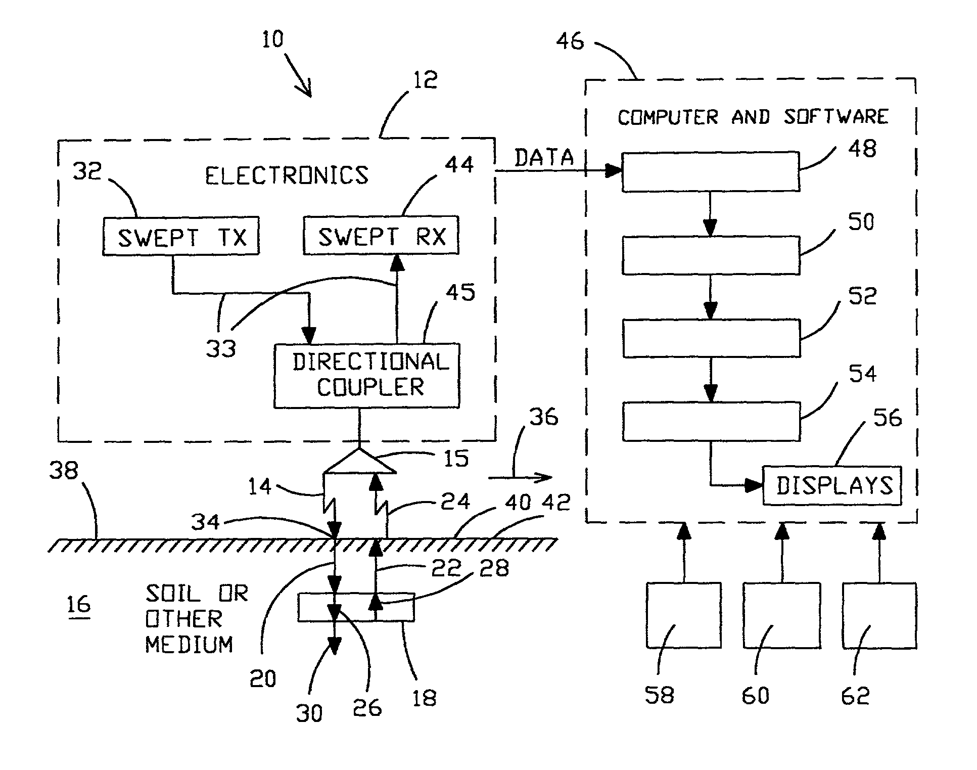
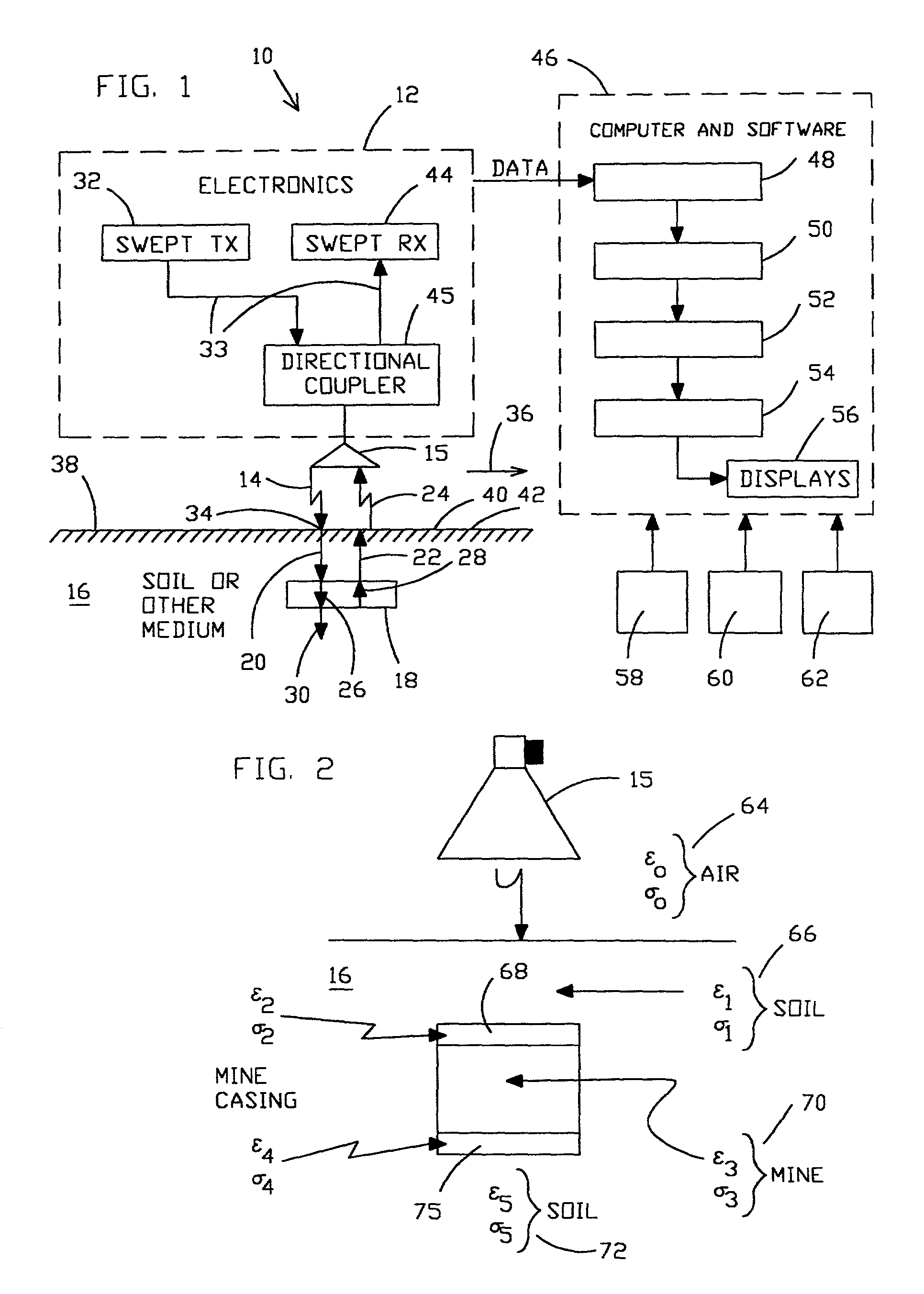
[0051] Referring now to the drawings and, more particularly, to FIG. 1 there is shown a transmitter / processor 10 in accord with the present invention. Electronics section 12 transmits broad band microwave signal 14 from antenna 15 directed into ground or soil 16 where an objec...


PUM


Abstract

Apparatus and methods are disclosed for detecting anomalies in microwave penetrable material that may be used for locating plastic mines or pipes underneath the ground. A transmitter is positioned at a plurality of different positions above the ground. A microwave signal is transmitted that is stepped over a plurality of frequencies. At each position, a plurality of reflections are received corresponding to each of the plurality of frequencies that were transmitted. A complex target vector may be produced at each position that contains complex values corresponding to magnitude, phase, and time delay for each of the plurality of reflections received at that location. A complex reference data vector may be produced, either based on predetermined values or based on data from the received plurality of reflections. A comparison is made between the complex target vector and the complex reference data vector to produce a channel vector. In one embodiment, an operator may be applied to the channel vector such as a complex filter matrix or to add a complex conjugate. A response signal is produced and anomalies are detected by variations in the response signal with respect to the plurality of positions.

Description

ORIGIN OF THE INVENTION[0001] The invention described herein was made in the performance of work under a NASA contract and is subject to the provisions of Section 305 of the National Aeronautics and Space Act of 1958, Public Law 85-568 (72 Stat. 435; 42 U.S.C. 2457).[0002] 1. Field of the Invention[0003] The present invention relates generally to detecting anomalies in microwave penetrable material and, more particularly, to the use of multiple reflections obtained at each of multiple positions in the microwave penetrable material for determining such anomalies. Anomalies of this type include but are not limited to plastic land mines, underground plastic pipes, liquid / foam interfaces, interfaces between geological materials, voids, and the like, which may be found in microwave penetrable environments that may camouflage such anomalies to a high degree.[0004] 2. Description of Prior Art[0005] On average, every twenty minutes someone in the world loses a limb to a landmine. Many landm...

Claims


Application Information

Patent Timeline
IPC IPC(8): F41H11/12G01S13/02G01S13/88G01V3/12
CPCF41H11/12G01V3/12G01S13/885G01S13/0209
Inventor ARNDT, G. DICKEYCARL, JAMES R.BYERLY, KENT A.NGO, PHONG H.STOLARCZYK, LARRY G.
Owner NASA
Learn More