
Tester with independent control of devices under test

a tester and independent control technology, applied in the field of testers, can solve the problems of high power consumption during burn-in testing, small current leakage of microprocessors, and significant cumulative leakage curren

Inactive Publication Date: 2002-09-05
ADVANCED MICRO DEVICES INC
View PDF0 Cites 55 Cited by
  • Summary
  • Abstract
  • Description
  • Claims
  • Application Information

AI Technical Summary

Problems solved by technology

For some devices, such as current microprocessors (e.g., the Athlon.TM. microprocessor available from Advanced Micro Devices, Inc.) the large number of transistors results in high power consumption during burn-in testing.
That is in part due to the fact that CMOS transistors typically utilized in such microprocessors leak a small amount of current even when "off".
Because of the large number of transistors found in current devices, even if the leakage current of each transistor is small, the cumulative leakage current can be significant.
In addition, there is a tendency for the faster parts to have higher leakage currents.
Another problem that is faced when testing high density devices in a burn-in environment is that operating the device at higher voltage and temperatures can result in the device operating in a region in which device operation is unstable.
More particularly, the device under test can enter a destructive positive feedback loop in which, as the part heats up, the transistors leak more current, which causes more heat, potentially resulting in thermal runaway.
Thermal runaway can result in melting the socket in which the device is being tested, damage to the test board or damage to the device under test.
Thus, no independent temperature control is possible and only limited action can be taken in response to unstable device operation.
While that may be sufficient for testing older technologies, it fails to allow the flexibility to test devices according to the unique testing parameters that may be required by the individual devices, especially in current burn-in test environments.

Method used


Image

  • Tester with independent control of devices under test
  • Tester with independent control of devices under test
  • Tester with independent control of devices under test

Examples


Embodiment Construction

)

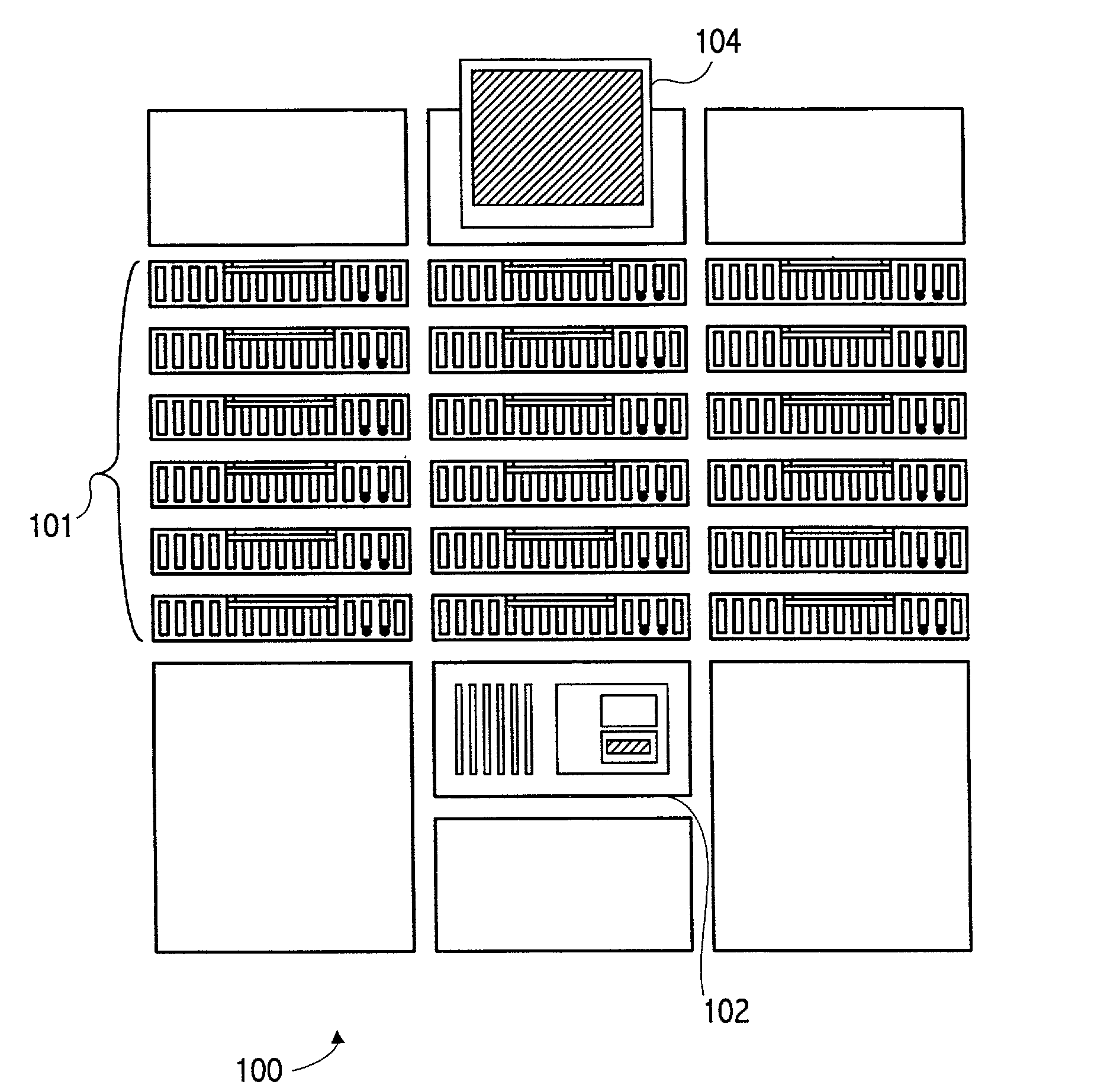
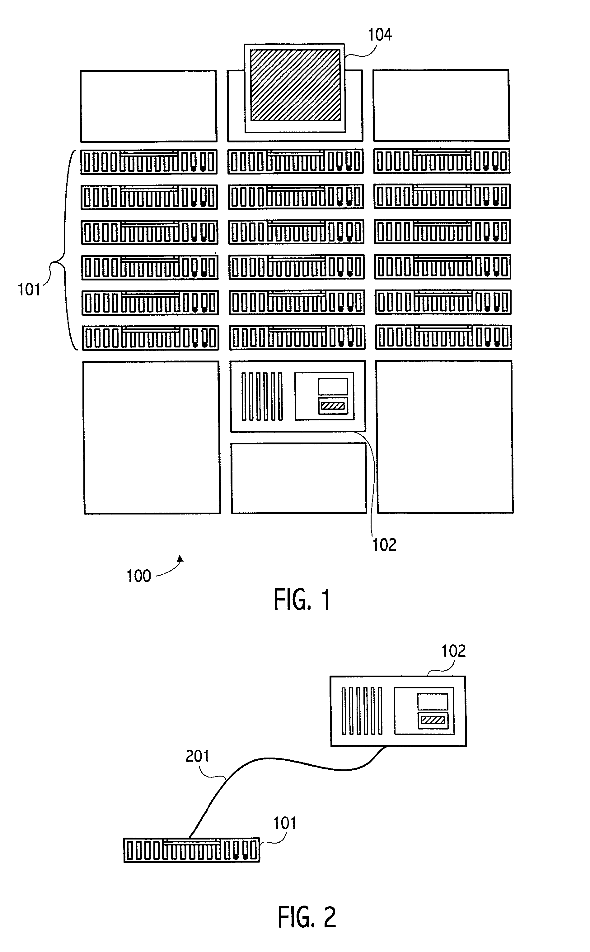
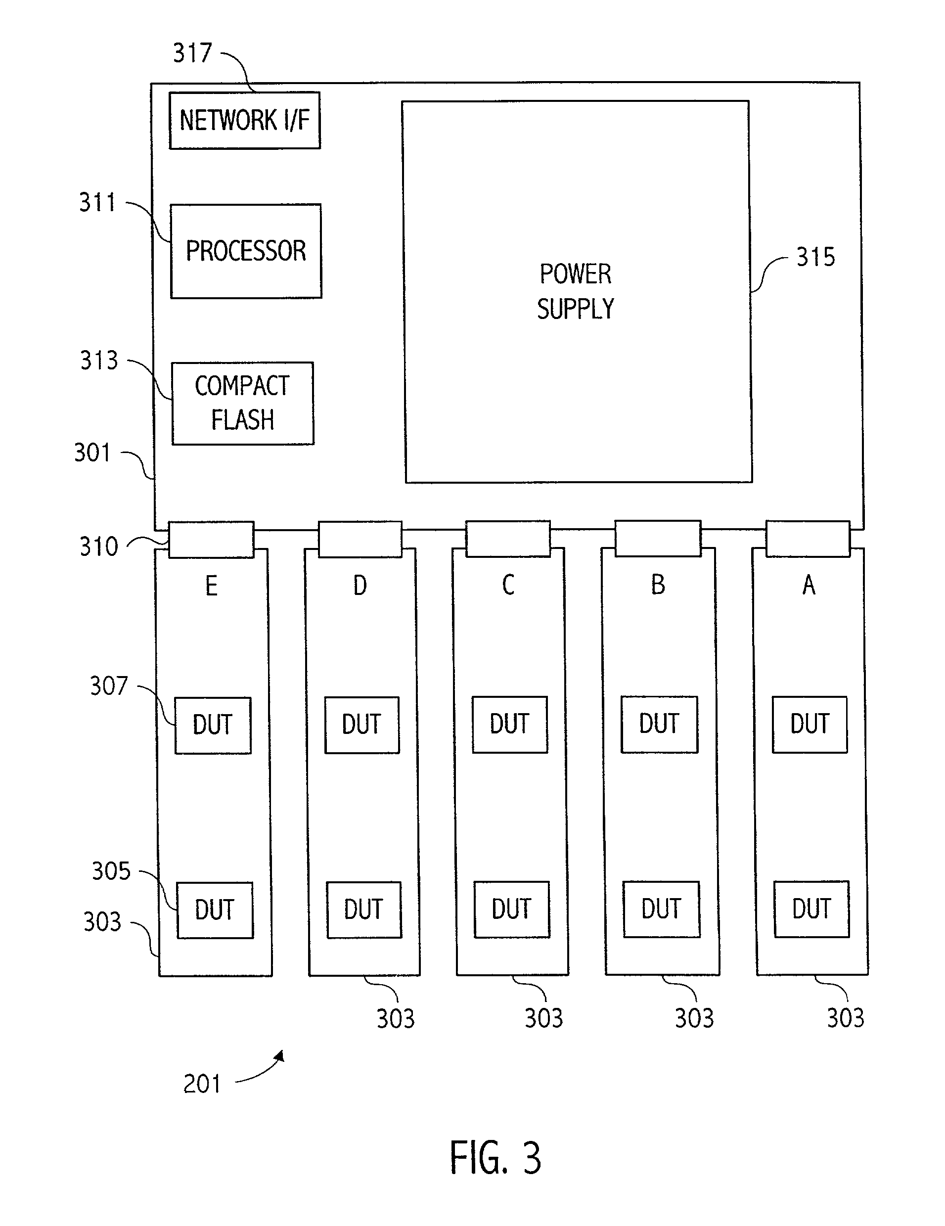
[0033] A high level illustration of an exemplary tester that can achieve independent control of the operational parameters such as temperature, clock frequency, voltage and test pattern being applied to a device under test (DUT) is illustrated in FIG. 1. Burn-in tester 100 includes a plurality of trays 101. In an exemplary embodiment, each of the trays can test up to 10 devices at one time. In the illustrated embodiment, tester 100 includes 18 trays 101 and thus can test 180 devices at one time. Overall control of the tester is provided by tester controller 102. In one embodiment, the tester shown is referred to as a cell and the test controller 102 is referred to as a cell host. Cell host 102 runs the test sequence for each device being tested in trays 101. Thus, cell host 102 controls the testing in all 18 trays. In an exemplary embodiment, as illustrated in FIG. 2, cell host 102 communicates via a network link 201 such as an Ethernet link with each tray. The cell host also provi...


PUM


Abstract

A burn-in tester that provides independent control of the devices under test. The various operating parameters such as temperature, voltage, frequency of operation or test pattern being applied can be independently changed on one device without affecting the operating parameters of the other devices. Thus, e.g., the amount of cooling applied to one device is independent of the amount of cooling applied to another device. In addition, the testing being done on each device may be independently controlled. Thus, a test can be changed on one of the devices under test without affecting the tests being run on any of the other devices. Similarly, the voltage and frequency of operation can be controlled independently to allow for changes to the voltage and / or frequency of one device without affecting those parameters on other devices being tested.

Description

[0001] 1. Field of the Invention[0002] This invention relates to testing of integrated circuits and more particularly to a tester providing independent control of devices under test.[0003] 2. Description of the Related Art[0004] In order to achieve higher reliability, manufacturers frequently employ "burn-in" testing to accelerate potential failure mechanisms. The tests are intended to weed out those parts that may be subject to infant mortality. Manufacturers typically utilize higher than normal supply voltages and temperatures during such tests and lower than normal frequencies. Burn-in testing normally tests the devices over long periods at the higher than normal voltages and temperatures. For some devices, such as current microprocessors (e.g., the Athlon.TM. microprocessor available from Advanced Micro Devices, Inc.) the large number of transistors results in high power consumption during burn-in testing. That is in part due to the fact that CMOS transistors typically utilized ...

Claims


Application Information

Patent Timeline
IPC IPC(8): G01R31/28
CPCG01R31/2874G01R31/2875G01R31/2879
Inventor MILLER, R. MARKDOLBEAR, TOMMARSHALL, JAYHOKANSON, PAUL
Owner ADVANCED MICRO DEVICES INC
Learn More