Apparatus and method for simulating a battery tester with a fixed resistance load
What is Al technical title?
Al technical title is built by PatSnap Al team. It summarizes the technical point description of the patent document.
a battery tester and fixed resistance technology, applied in the field of simulating a battery tester with a fixed resistance load, can solve the problems of reducing affecting the service life of the battery tester,
Inactive Publication Date: 2006-10-03
MIDTRONICS
View PDF322 Cites 111 Cited by
Summary
Abstract
Description
Claims
Application Information
AI Technical Summary
This helps you quickly interpret patents by identifying the three key elements:
Problems solved by technology
Method used
Benefits of technology
Problems solved by technology
Because this tester has a fixed load resistor that discharges batteries at sizable rates (for example, 150 amperes for 5–6 seconds), the tester is rather bulky and may get hot with repeated tests.
Also, waiting for the completion of the load and the recovery time takes a moderate amount of time and further depletes battery charge.
Furthermore, if the tester is to be powered by the battery to be tested, then heavy loads can drain a weak or discharged battery causing the tester to lose sufficient power to keep its control circuits running thereby causing a reset.
Method used
Image
Click on the blue label to locate the original text in one second.
Reading with bidirectional positioning of images and text.
Examples
Embodiment Construction
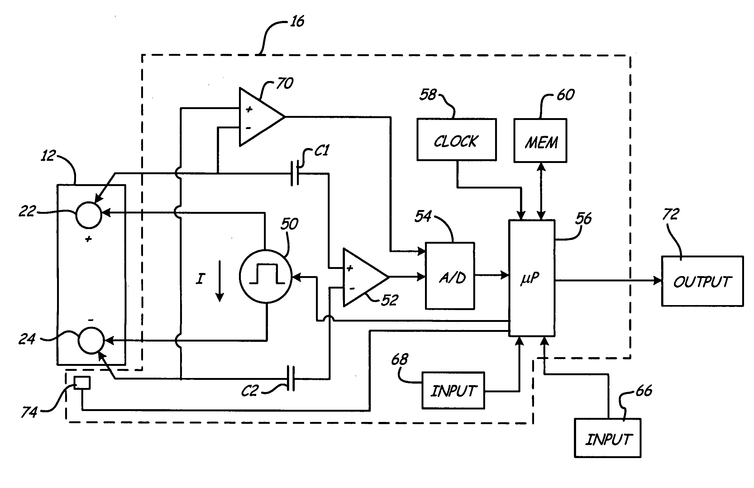
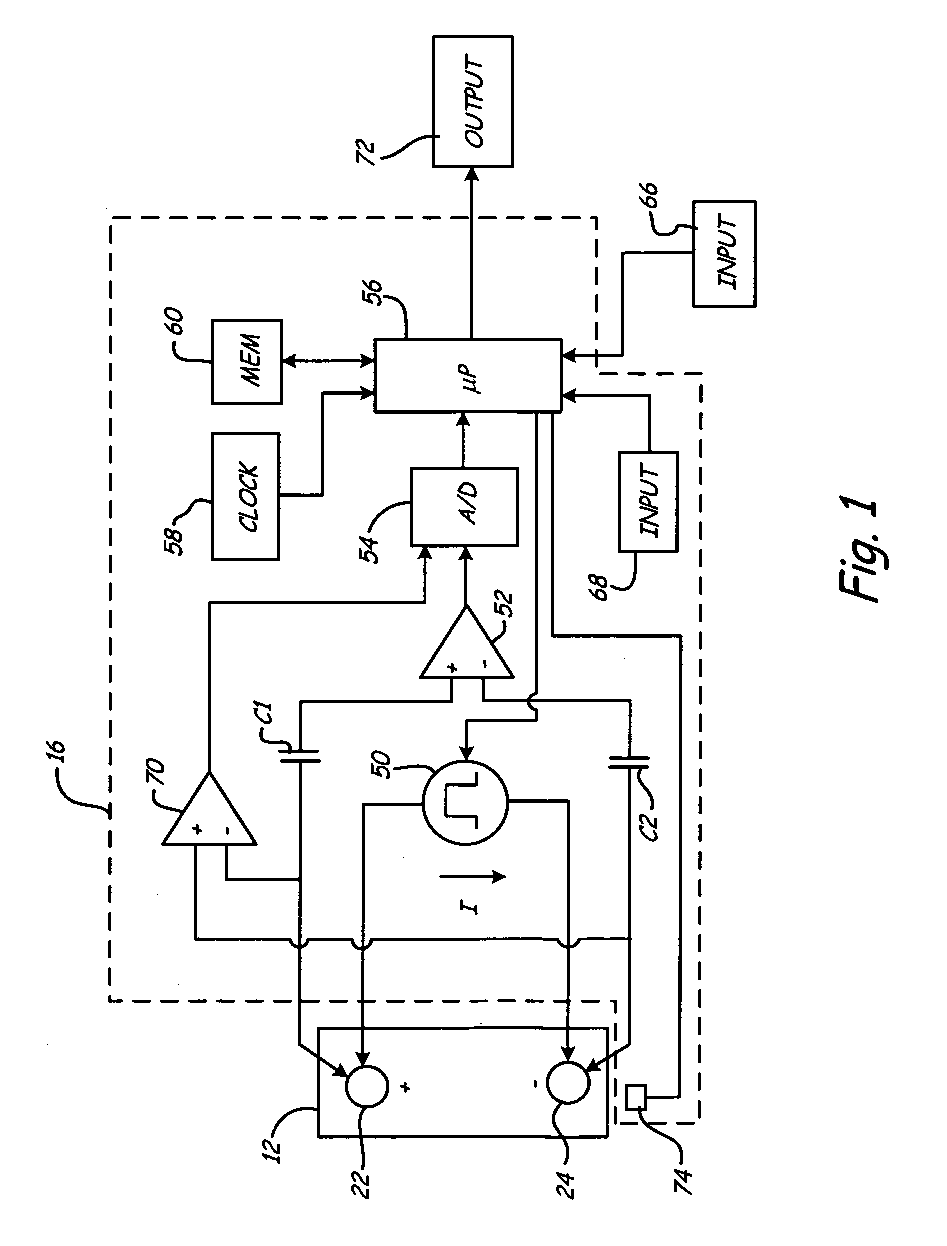
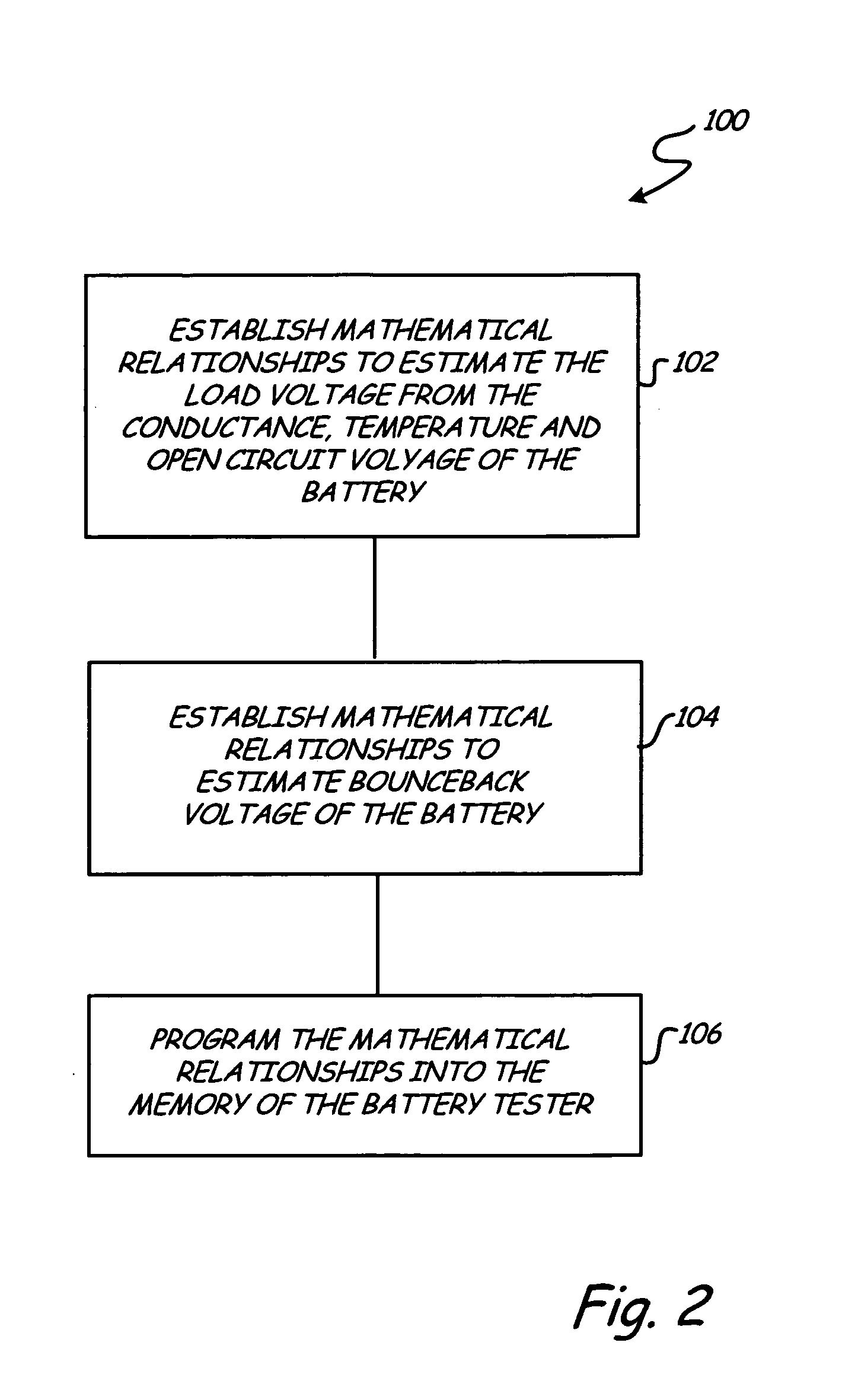
[0011]The present invention provides an apparatus and method for simulating a battery tester with a fixed resistance load, such as a Japanese load tester that rates the strength of Japanese batteries that are categorized under the Japanese Industrial Standard (JIS). A battery tester of the present invention assesses a dynamic parameter, such as conductance, of a battery rated according to Japanese Industrial Standards (JIS) and, together with the resistance of the tester load to be simulated, an open circuit voltage and the temperature of the JIS rated battery, outputs calculated values that are used to rate the strength of the JIS rated battery by categories of JIS group size numbers. In addition, the tester can be used for non-JIS batteries by using reference CCA (cold cranking amps) ranges for each group size.
[0012]FIG. 1 is a simplified block diagram of battery test circuitry 16 in accordance with an embodiment of the present invention. Apparatus 16 is shown coupled to battery 1...
PUM
Property
Measurement
Unit
voltage
aaaaa
aaaaa
load voltage
aaaaa
aaaaa
load voltage
aaaaa
aaaaa
Abstract
A method and apparatus for simulating a battery tester with a fixed resistance load, such as a widely used Japanese load tester that rates the strength of Japanese batteries that are categorized under the Japanese Industrial Standard (JIS), are provided. This invention simulates such a device without invoking large current loads, yields familiar results, utilizes an existing database and provides more conclusive testing. The method includes measuring an open circuit voltage (OCV), temperature and a dynamic parameter of the battery. A load voltage of the battery is estimated as a function of the measured battery dynamic parameter, the OCV, the load resistance value of the load tester and the battery temperature. A bounceback voltage (BBV) of the battery is then predicted. The BBV, the load voltage and the battery temperature are utilized to rate the strength of the battery.
Description
BACKGROUND OF THE INVENTION[0001]The present invention relates to testing storage batteries. More specifically the present invention relates to simulating a battery tester with a fixed resistance load such as a widely used Japanese load tester that rates the strength of Japanese batteries that are categorized under the Japanese Industrial Standard (JIS). The present invention simulates such a device without invoking large current loads, yields familiar results, utilizes an existing database and provides more conclusive testing.[0002]Electronic battery testers are used to test storage batteries. Various examples of such testers are described in U.S. Pat. No. 3,873,911, issued Mar. 25, 1975, to Champlin, entitled ELECTRONIC BATTERY TESTING DEVICE; U.S. Pat. No. 3,909,708, issued Sep. 30, 1975, to Champlin, entitled ELECTRONIC BATTERY TESTING DEVICE; U.S. Pat. No. 4,816,768, issued Mar. 28, 1989, to Champlin, entitled ELECTRONIC BATTERY TESTING DEVICE; U.S. Pat. No. 4,825,170, issued A...
Claims
Application Information
Patent Timeline
Application Date:The date an application was filed.
Publication Date:The date a patent or application was officially published.
First Publication Date:The earliest publication date of a patent with the same application number.
Issue Date:Publication date of the patent grant document.
PCT Entry Date:The Entry date of PCT National Phase.
Estimated Expiry Date:The statutory expiry date of a patent right according to the Patent Law, and it is the longest term of protection that the patent right can achieve without the termination of the patent right due to other reasons(Term extension factor has been taken into account ).
Invalid Date:Actual expiry date is based on effective date or publication date of legal transaction data of invalid patent.