
Impinging stream dryer

a dryer and stream technology, applied in drying machines, lighting and heating apparatus, furniture, etc., can solve problems such as thermal endangered, impairing drying, and affecting the drying effect, and achieving the effect of reducing the number of nozzles, and reducing the drying

Inactive Publication Date: 2002-08-29
VOITH PATENT GMBH
View PDF4 Cites 2 Cited by
  • Summary
  • Abstract
  • Description
  • Claims
  • Application Information

AI Technical Summary

Benefits of technology

[0011] Moreover, in the case of a broader design of the cooled area of the support belt, i.e., cooling into the edge area of the fibrous material web, no readjustment is necessary in the case of changing web widths of the fibrous material web. It is an advantage particularly for this if the cooling of the support belt occurs after the transfer of the fibrous material web from it to a following unit.
[0012] In general, the edge of the support belt is thereby cooled in an area of between about 50 and 1000 mm. Above all if the cooled area is very wide or even extends over the entire support belt, it is often advantageous if the cooling of the support belt occurs at different intensities in cooling zones delineated transverse to the web running direction. This makes it possible to adapt the necessary cooling intensity, for instance, to the local temperature of the support belt. There are also advantages here if the cooling capacity assigned to the cooling zones can be controlled separately. Here the cooling of the support belt is made by at least one cooling device in the form of liquid and / or compressed air nozzles. To this end, a liquid is to be fed to the liquid nozzles, the boiling temperature of which is lower than the maximum admissible temperature of the support belt, preferably water or alcohols, such as polyethylene glycol. With adequate liquid feed, this evaporative cooling prevents the temperature of the support belt rising above the boiling temperature of the liquid. In order to relieve the surroundings of the machine and to prevent a rewetting of the fibrous material web, the liquid that rebounded from the support belt and / or the liquid mist emanating from it should be drawn off by control elements and / or collecting devices and / or suction devices.
[0013] To influence the cooling capacity, it should be possible to control the pressure and / or the flow rate of the liquid and / or compressed air nozzles preferably individually or zonally. This makes it possible to adjust the cooling capacity depending on the heating capacity of the impinging stream dryer, preferably to control it and / or regulate it depending on the temperature of the support belt, particularly the temperature of the affected cooling zone, and / or to control it depending on an upstream tear recognition of the fibrous material web. To this end, temperature sensors to measure the temperature of the support belt in the web running direction in front of and, under certain circumstances, after the cooling device are helpful, and they should be arranged in particular opposite the edge of the support belt. For comparison purposes, the measurement of the temperature of the support belt in the central area is advantageous.
[0014] In general, the supporting band should be embodied as a screen. Moreover, it is advantageous for ensuring a stable action of the support belt and thus also of the fibrous material web and with regard to the distance from the impinging stream dryer, if the support belt is guided over a rotating backup roll during the impinging of the fibrous material web with the hot air and / or superheated steam impinging stream. One constructively simple solution results when the hot air and / or superheated steam impinging stream is produced by a drying hood arranged in a circumferential area of the backup roll.

Problems solved by technology

As the fibrous material web provides a sufficient heat insulation towards the support belt, essentially only the areas of the support belt that it does not cover, i.e., the edges, are thermally endangered.
In order to deal with this, the width of the impinging stream dryer is mostly limited to the web width; however, this entails difficulties or considerable expense with changing width of the fibrous material web.
However, the finding was that this impairs the drying result.

Method used


Image

  • Impinging stream dryer
  • Impinging stream dryer

Examples


Embodiment Construction

[0045] The particulars shown herein are by way of example and for purposes of illustrative discussion of the embodiments of the present invention only and are presented in the cause of providing what is believed to be the most useful and readily understood description of the principles and conceptual aspects of the present invention. In this regard, no attempt is made to show structural details of the present invention in more detail than is necessary for the fundamental understanding of the present invention, the description taken with the drawings making apparent to those skilled in the art how the several forms of the present invention may be embodied in practice.

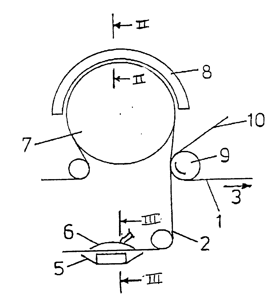
[0046] The impinging stream dryer is part of a paper machine for drying the fibrous material web 1 and is formed essentially by a rotating backup roll 7 and a drying hood 8. The drying hood 8 is arranged at a distance of a few centimeters from the backup roll 7 and extends over a large part of the circumference of the ba...


PUM


Abstract

Impinging stream dryer and process for drying a fibrous material web that includes an air-permeable, endlessly circulating support belt structured and arranged to support a side of the fibrous material web, a device for impinging an opposite side of the fibrous material web with an impinging stream, and a belt cooling device arranged to cool at least an edge zone of said support belt that is directly impinged with the impinging stream.

Description

[0001] The present application claims priority under 35 U.S.C. .sctn.119 of German Patent Application No. 101 09 525.2, filed on Feb. 28, 2001, the disclosure of which is expressly incorporated by reference herein in its entirety.[0002] 1. Field of the Invention[0003] The invention relates to an impinging stream dryer for drying a paper, cardboard, tissue or another fibrous material web, in which the fibrous material web is impinged on one side with a hot air and / or superheated steam impinging stream and is supported on the opposite side on an air-permeable, endlessly circulating support belt.[0004] 2. Discussion of Background Information[0005] Such impinging stream dryers are known, for example, from DE 19841768 A1, where they are part of the drying section of a paper machine. The temperature of the hot air or the superheated steam can thereby reach values of between about 300.degree. and 500.degree. C. In contrast, the temperature stability of the relevant support belts, particula...

Claims


Application Information

Patent Timeline
IPC IPC(8): D21F5/04D21F5/18
CPCD21F5/044D21F5/18
Inventor KAHL, PETEROECHSLE, MARKUSMAYER, ROLAND
Owner VOITH PATENT GMBH
Learn More