
Variable reactive force arrangement for pole mounted, pressure washing lances

a technology of reactive force and pressure washing lance, which is applied in the direction of valve operation/release device, cleaning using liquids, transportation and packaging, etc. it can solve the problems of difficult handling of the pole, undesirable control force upon the operator, and difficulty in maneuvering the telescoping pole when the target surface is relatively distant from the operator, so as to reduce the operator force and reduce the effort. , the effect of lessening the effor

Active Publication Date: 2009-12-01
BOEKELMAN TIMOTHY RAYMOND
View PDF51 Cites 8 Cited by
  • Summary
  • Abstract
  • Description
  • Claims
  • Application Information

AI Technical Summary

Benefits of technology

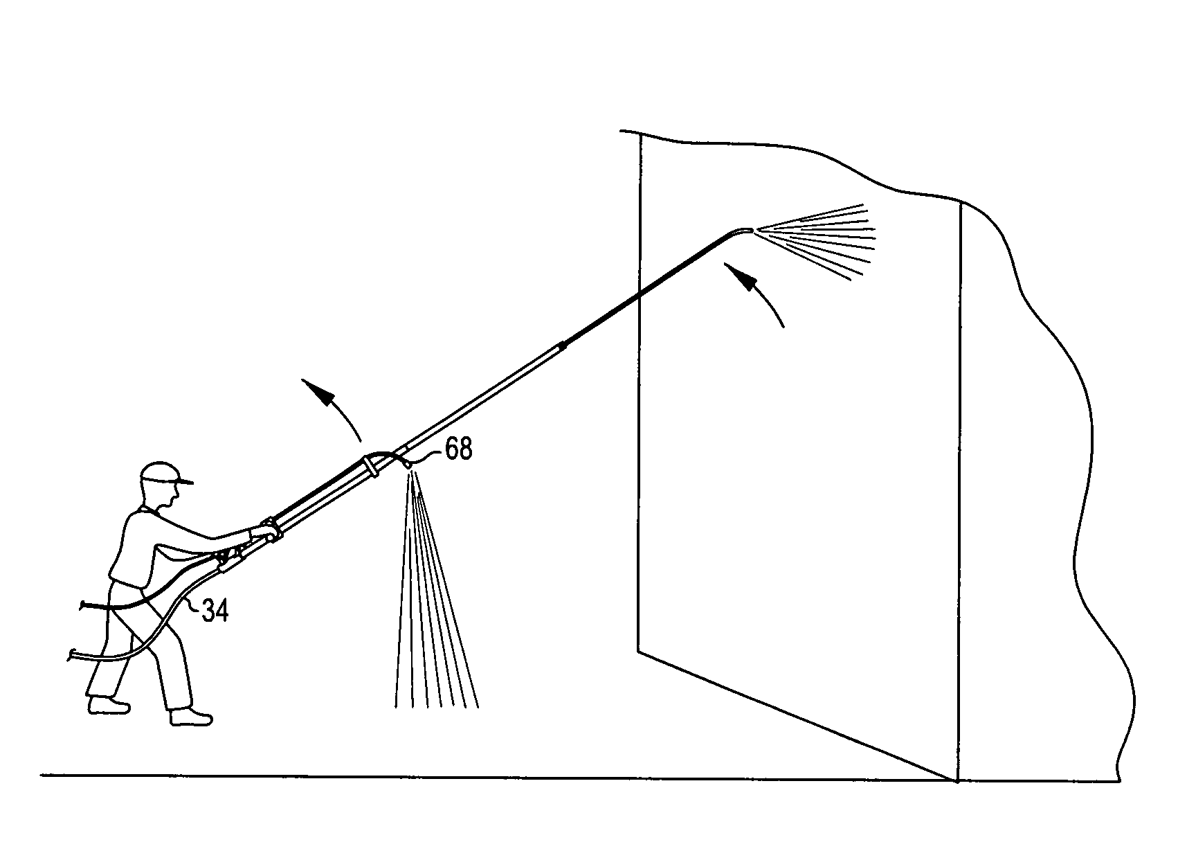
"The invention is about a device that controls the reactive thrust of a pressure washer lance during operation. The device includes a bypass valve and a dump tube that work together to control the flow of fluid from the pressure pump. The bypass valve can direct the fluid either to the primary output or the secondary output, and the secondary fluid can be ejected through either a separate nozzle or an auxiliary nozzle in the dump tube. The device can also minimize the kinetic energy of the secondary fluid and maximize the reactive force generated by the lance. The invention provides a more effective and practical way to control the reactive thrust of a pressure washer lance."

Problems solved by technology

However, maneuvering of the telescoping pole when the target surface is relatively distant from the operator is less than easy.
This makes the pole harder to handle and creates undesirable control force upon the operator.
Also, if the nozzle becomes misaligned, the force of the pressure will work against the operator, and the operator may have to completely interrupt the high pressure water and realign the nozzle.
In addition, telescoping poles are notoriously heavy and an operator must usually lift the pole into the desired cleaning position, then operate the on / off trigger to start the cleaning process.
Moreover, manually holding the on / off trigger in the on position can quickly tire the operator's hands, which also makes it more difficult to wrangle the pole to the desired positions.

Method used


Image

  • Variable reactive force arrangement for pole mounted, pressure washing lances
  • Variable reactive force arrangement for pole mounted, pressure washing lances
  • Variable reactive force arrangement for pole mounted, pressure washing lances

Examples


Embodiment Construction

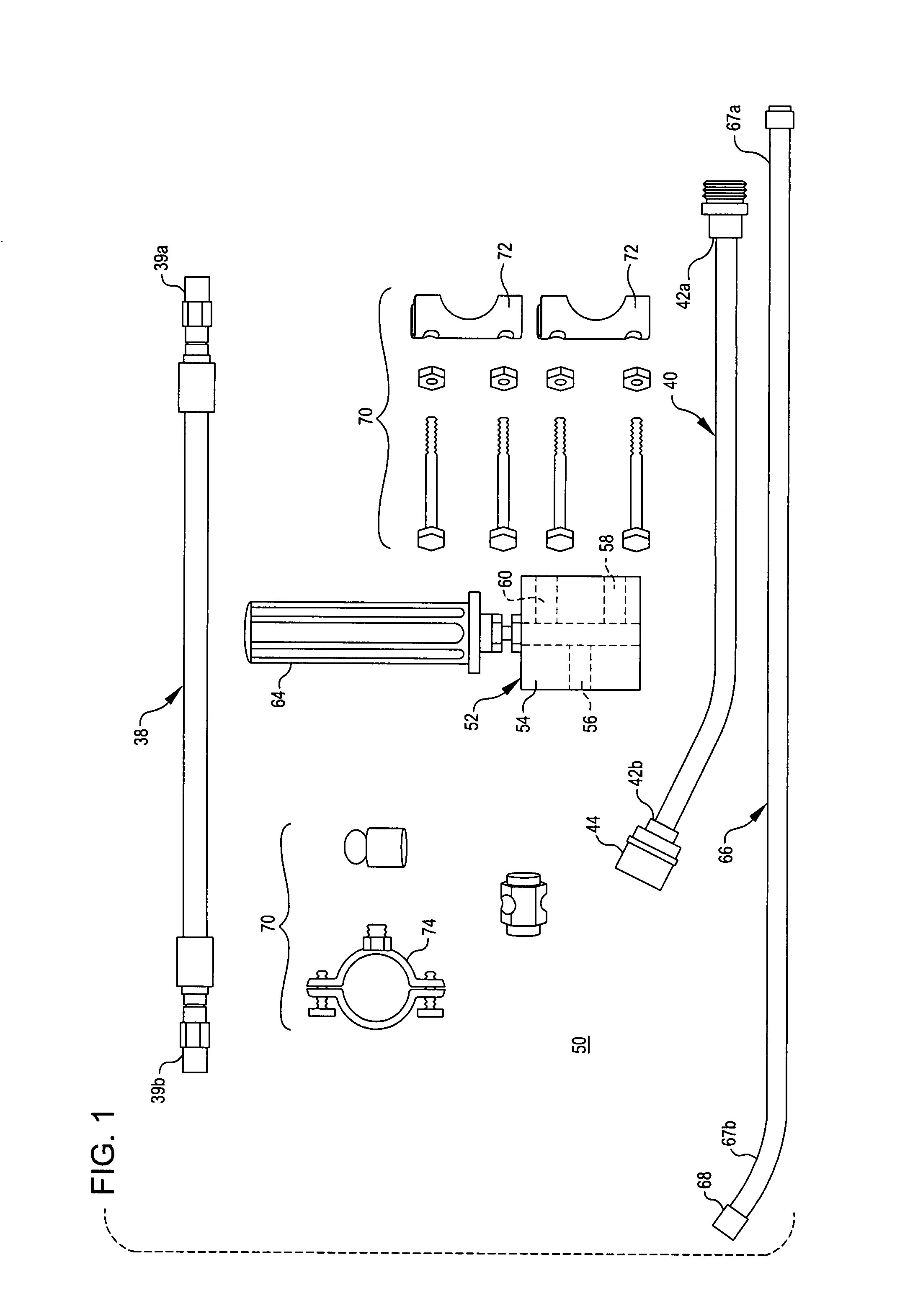
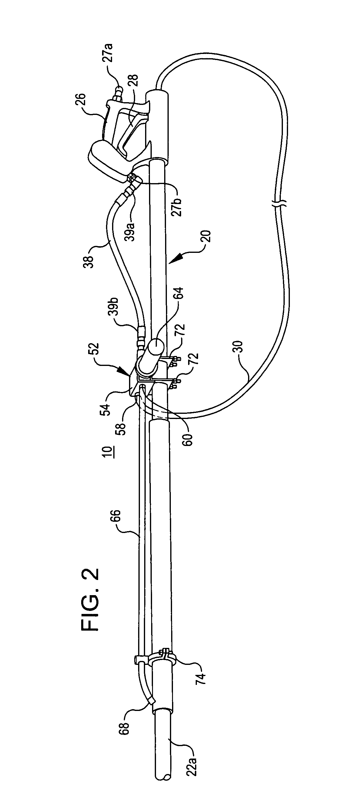
[0021]Turning then to the several drawings, wherein like numerals indicate like parts, and more particularly to FIG. 1, aftermarket kit 50 according to the invention is shown. Kit 50, also referred to as variable reactive force arrangement 50, comprises bypass hose 38, lance 40, bypass valve 52, dump tube 66 and associated mounting hardware collectively referred to as hardware 70. Unless otherwise noted or contrary to industry standard, all metal parts are preferably constructed from brass or chrome plated brass, and all flexible parts are preferably constructed from rubber derivatives, and are capable of operating with working pressures up to 4,000 psi.

[0022]Bypass valve 52 comprises housing 54, which defines inlet 56, primary outlet 58 and secondary outlet 60. A diverter (not shown) in housing 54, variably exposes primary and / or secondary outlets 58 and 60, respectively, to inlet 56 when diverter handle 64 is operated. As will be described in more detail below, bypass valve 52 mod...


PUM


Abstract

Apparatus and methods for establishing a controllable reactive thrust in a pressure washing lance (40) linked to an extension member (20) through use of a variable bypass valve (52) and dump tube (66) combination. The bypass valve (52) is coupled to a source of high pressure fluid by a system high pressure or primary circuit (26,38). The bypass valve (52) preferably has at least one bypass input (56), which is intended to be fluidly coupled with the high pressure or primary circuit (38), and at least one each of a bypass primary output (58) and a bypass secondary output (60). Operation of the bypass valve (52) selectively couples the bypass input (56) with the bypass primary output (58) and / or the bypass secondary output (60). Fluid from the bypass primary output (58) is directed to the lance ejection nozzle (44) while fluid from the bypass secondary output (60) (secondary fluid) is directed to the dump tube (66). Dump tube output can also be modified to provide a reactive thrust and vectored by adjustment of the tube bend (67b) and a nozzle (68) thereon.

Description

[0001]This is a continuation application that claims benefit, under 35 USC §120, of co-pending International Application PCT / US 2007 / 010504, filed on 30 Apr. 2007, designating the United States, which claims priority to U.S. Provisional Application No. 60 / 796,788, filed on 01 May 2006, which applications are incorporated herein by reference.BACKGROUND OF THE INVENTION[0002]In the field of telescoping pressure washing poles, conventional arrangements comprise a telescoping pole having a lance with a nozzle at a distal end, a high pressure hose disposed within the body of the telescoping pole, an on-off trigger at a proximal end for user operation, and an open end at the proximal end of the pole so that excess fluid in the high pressure hose can be ejected when collapsing the pole or taken in when extending the pole. The free end of the high pressure hose is then attached, either directly or indirectly, to a source of high pressure fluid, commonly water or water mixed with a detergent...

Claims


Application Information

Patent Timeline
Patent Type & Authority Patents(United States)
IPC IPC(8): B05B9/00
CPCB08B3/026B08B3/028B05B9/01B05B15/068B05B1/30Y10T137/85994B05B15/656
Inventor BOEKELMAN, TRACY
Owner BOEKELMAN TIMOTHY RAYMOND
Learn More