
Method and device for determining the accuracy of a fold position

a technology of folding accuracy and measurement method, which is applied in the direction of paper/cardboard containers, instruments, transportation and packaging, etc., can solve the problems of time-consuming and tiresome work, which can take up to several hours a day, and human visual assessment of folding accuracy involves the risk of assessment errors and manipulation, and is possibily involuntary

Inactive Publication Date: 2002-08-22
HEIDELBERGER DRUCKMASCHINEN AG
View PDF0 Cites 18 Cited by
  • Summary
  • Abstract
  • Description
  • Claims
  • Application Information

AI Technical Summary

Benefits of technology

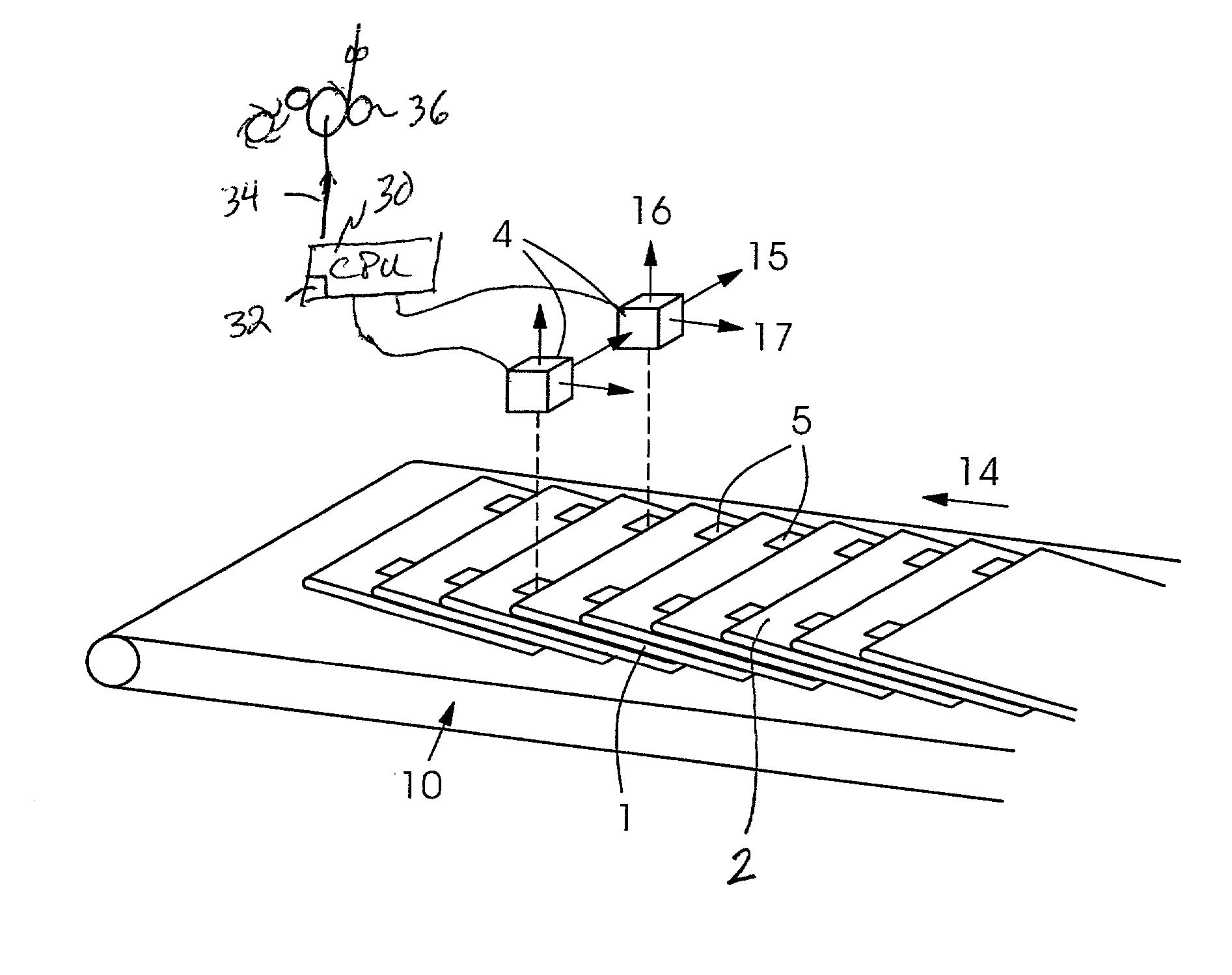
[0006] The use of sensors and the evaluation via a computer permit a fast analysis of the folding accuracy so that, for example, the number of copies of the printed product which can be examined in the same period of time is increased by a factor of 10 or 20. Due to the fast analysis, it is possible to carry out a great number of tests, for example, with different types of paper or numbers of pages to gather knowledge about the folding accuracy in the whole possible range of producible products on the folding apparatuses. Via further tests, it is possible to extend the knowledge about the dynamics of the folding apparatus, for example, about the folding precision as a function of the speed. Since the device according to the present invention permits examination of a large number of test copies, the statistic meaningfulness of the calculated folding accuracy is increased. Moreover, this great number of examined copies makes it possible to gain knowledge about errors which occur with very small frequencies. Furthermore, the present invention can be used to provide service technicians or operators of the folding apparatus with an aid for error diagnosis. Using sensors, it is possible, moreover, to increase the measuring accuracy and to avoid the risk of human assessment errors or manipulations. The integration of a marking field in the print allows the printing accuracy to be fed back to the folding apparatus, thereby allowing measures for increasing the folding accuracy to be initiated in response to the occurrence of errors (such as oblique folds, overhanging paper), for example, an error correction using the folding mechanism or a speed control of the conveying element conveying the stream of shingles.
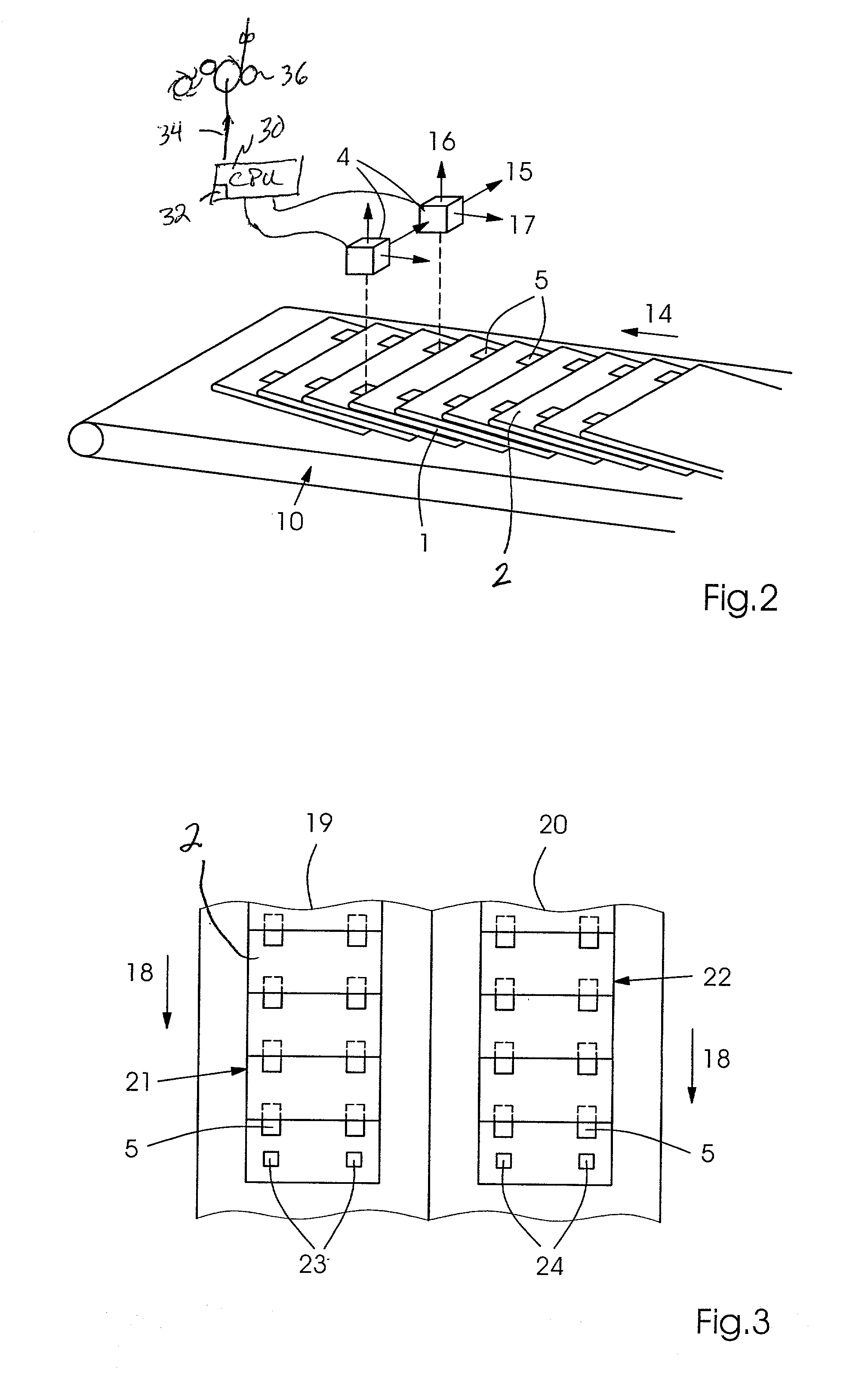
[0007] In a further embodiment of the basic idea of the present invention, the markings can include at least two, preferably rectangular dark areas which are preferably arranged on both sides of a copy of a printed product as viewed in the direction of conveyance. In this context, it is an advantage that the, for example, black areas constitute a well-detectable contrast over white background and that each rectangular black area features a sharp edge to the light, for example, white surroundings. In lieu of the dark areas, light markings can be used as well if the background, in particular the edge of the printed product, is dark up to the fold. Moreover, it is conceivable for register marks or print control bars, which are already applied to the printing-material web from which the printed products are produced, to be used as markings. In any case, the intention is to ensure a well detectable contrast between the marking and the background. The arrangement of the two areas on both sides of a copy at a distance from each other which nearly corresponds to the size of the printed product involves the advantage that the as large as possible a distance permits detection of even a slight obliqueness of the fold.
[0013] The height-adjustment capability of the sensors permits an accurate focusing of the contrasts to be detected. The height can be adapted, in particular to the thickness of the printed products. Lower-contrast transitions between the markings and the background can be resolved better via an exact focusing. The adjustment settings for the sensors can be stored in advance for known or common kinds of printed products. They can then be retrieved in the case of a change between the different printed products, and an automatic adjustment of the sensors can take place.

Problems solved by technology

This is time-consuming and tiresome work which can take up to several hours a day.
Moreover, human visual assessment of the folding accuracy involves the risk of assessment errors and of manipulations, possibily involuntary, of the results.

Method used


Image

  • Method and device for determining the accuracy of a fold position
  • Method and device for determining the accuracy of a fold position
  • Method and device for determining the accuracy of a fold position

Examples


Embodiment Construction

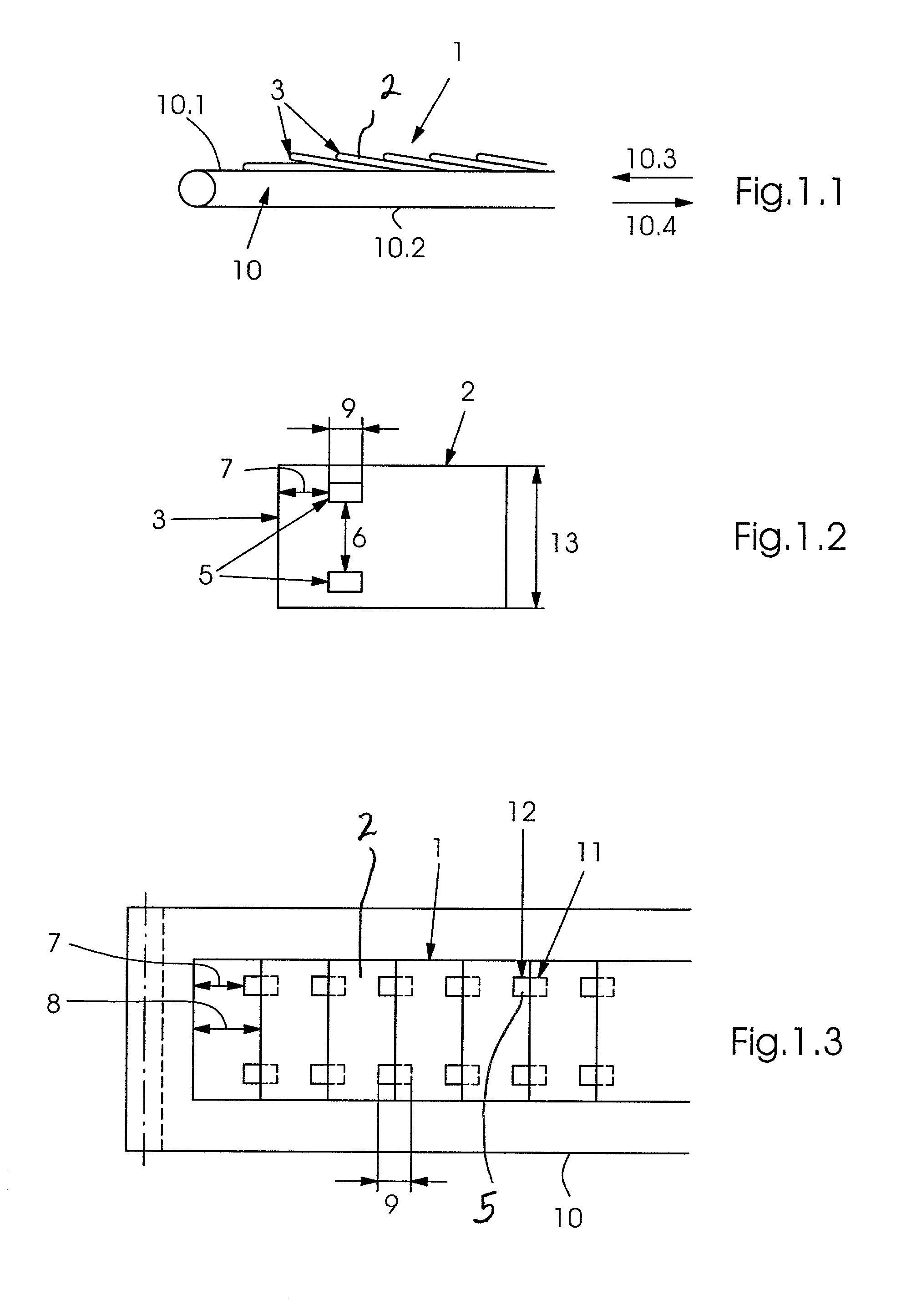
[0027] FIG. 1.1 shows shingled printed products in a shingle stream 1 which feature a fold 3 and are situated on a conveying element 10 composed, for example, of a conveyer band or belts, which may for example in a continuous loop. Printed products 2 are situated on upper side 10.1 of the conveyer band and preferably have a moving direction 10.3 with folding spine 3 being in a front or leading position. Conveyer band lower side 10.2 moves in a direction opposite thereto (in direction 10.4). In the shingle stream shown in FIG. 1.1, printed products 2 are arranged in an overlappingly shingled manner, the leading edge of a following printed product 2 coming to rest on the upper side of the preceding printed product 2.

[0028] FIG. 1.2 depicts a single printed product 2 which is provided with a fold 3 and features two markings 5 which are, for example, rectangular. Distance 6 of the two markings 5 is slightly smaller than size 13 of the printed product. Markings 5 have a distance 7 from f...


PUM


Abstract

The present invention relates to a method and a device for analyzing the accuracy of a fold (3) which is produced via a folding apparatus for printed products. In the process, with the printed products (1) being shingled, sensors (4) detect the position of the fold with respect to markings (5) which are printed onto the printed product, the folding accuracy and other quantities connected therewith being determined therefrom with the aid of computers.

Description

BACKGROUND INFORMATION[0001] The present invention relates to a method and a device for determining the accuracy of a fold position which is produced, for example, via a folding apparatus for printed products.[0002] German Patent Application No. 197 43 020 relates to a separating device for printed products having a plurality of conveying elements for conveying the printed products. A series of printed products at least partially overlapping each other in a shingle-like manner and which are received from a pre-processing machine pass through the separating device and are converted to a series of spaced-apart printed products for feeding into a post-processing machine. The separating device possesses a detector element for detecting the degree of overlapping of the individual printed products overlapping each other in a shingle-like manner and an additional conveying element for accelerated conveyance of individual printed products for correcting the degree of overlapping or the dist...

Claims


Application Information

Patent Timeline
IPC IPC(8): B65H7/06B65H29/66B65H43/00
CPCB65H29/66B65H43/00B65H2511/22B65H2511/512B65H2511/522B65H2220/01B65H2220/03
Inventor SILVESTRE, ALAIN
Owner HEIDELBERGER DRUCKMASCHINEN AG
Learn More