
Imaging mass spectrometer

Inactive Publication Date: 2007-05-24
SHIMADZU CORP
View PDF7 Cites 65 Cited by
  • Summary
  • Abstract
  • Description
  • Claims
  • Application Information

AI Technical Summary

Benefits of technology

[0014] In the imaging MS apparatus according to the present invention, mass analysis is performed with scanning, with a laser beam spot, on a predetermined region, which is selected beforehand based on the image extracted information of the sample generated. The analysis of the target region, therefore, can be accomplished in a short period of time. In many samples, a region is defined by the color or the brightness, which contains substantially the same or similar components, so the analysis can be expedited. Moreover, by computing the sum (or the average) of the results in the region, the analysis of the components present in the region can be effected at a high level of sensitivity (S / N ratio). By computing complex statistical values, such as variances, more in-depth information related to the presence of the components in the sample can be obtained.
[0015] For example, performing a staining process on a biological sample using a certain dye or the like enables the coloring of specific tissues. The use of this apparatus of the present invention, therefore, enables the analysis of the components that are present in the tissue quickly and with a high level of accuracy.

Problems solved by technology

Certain proteins and saccharides, however, are sparsely present in a biological sample, which makes it difficult for mass spectrometry to obtain a sufficient level of target signal intensity for reliable results.

Method used


Image

  • Imaging mass spectrometer
  • Imaging mass spectrometer
  • Imaging mass spectrometer

Examples


Embodiment Construction

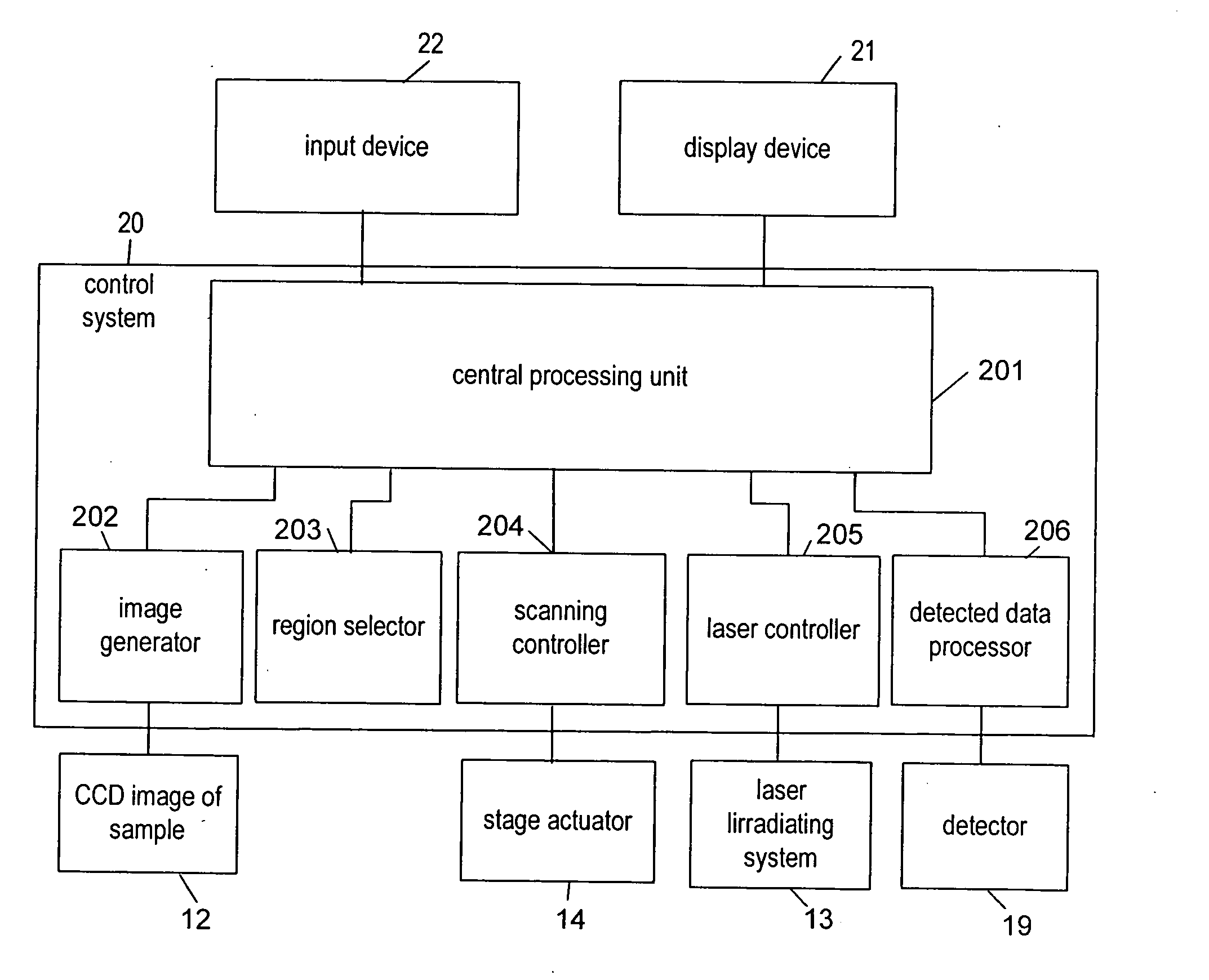
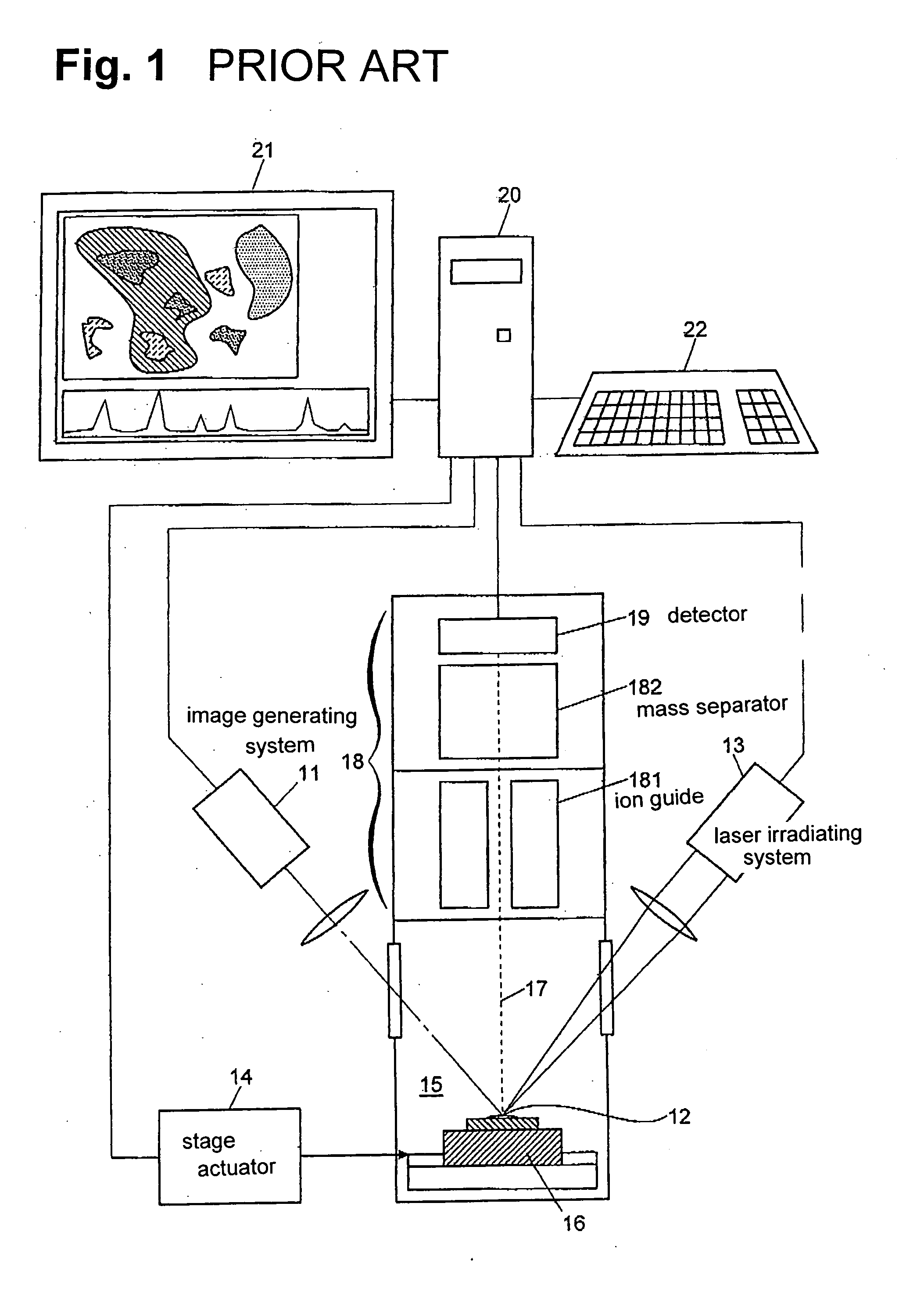
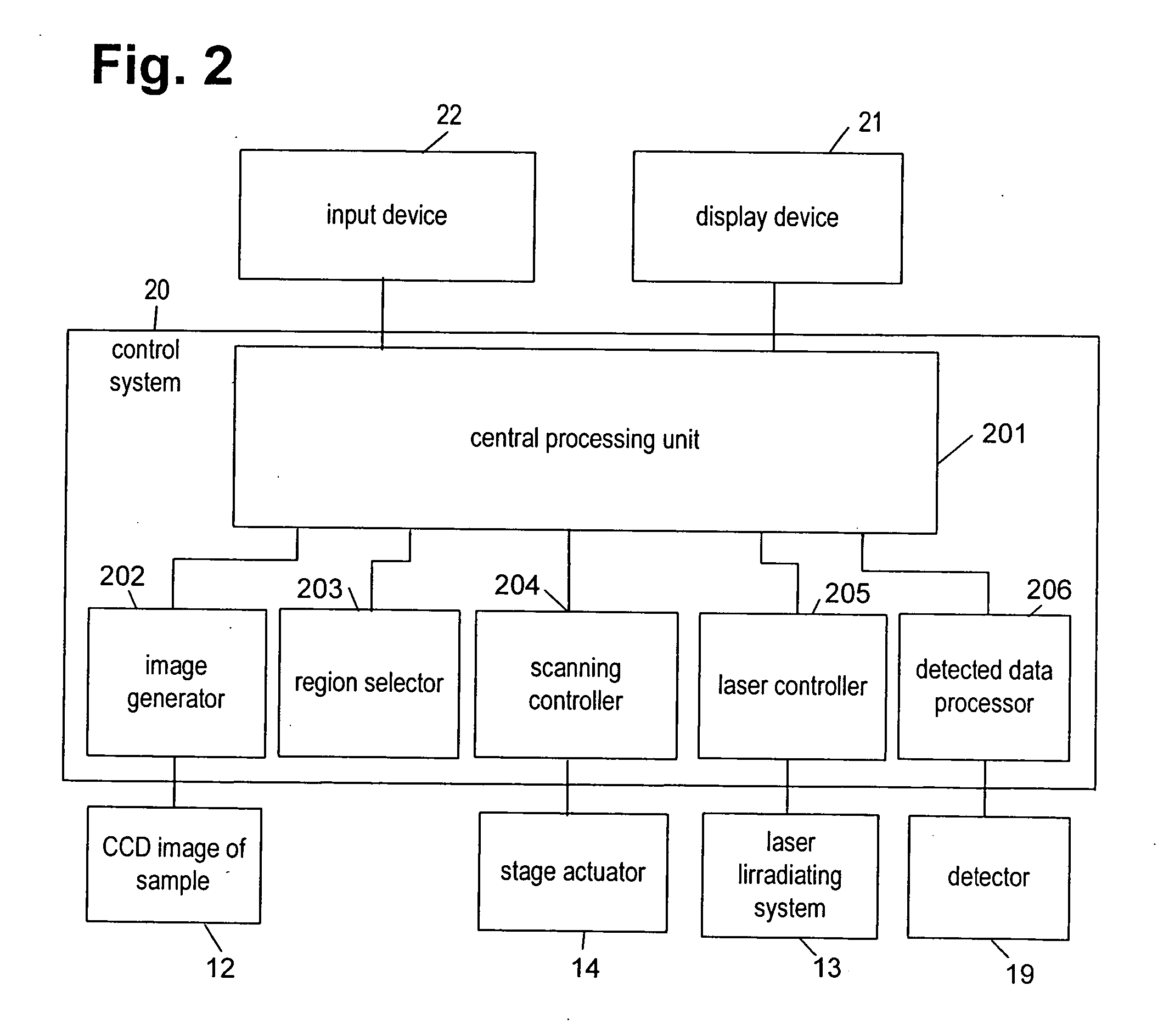
[0022] A microscope mass spectrometer, which is one example of the present invention, will be explained below. The hardware composition of the microscope mass spectrometry apparatus is essentially the same as the aforementioned conventional microscope. In other words, the main body, as shown in FIG. 1, comprises a sample chamber 15 and a mass analyzer 18, an image generating system 11 for viewing and generating the image of a sample through a window provided therein, and a laser irradiating system 13 for irradiating a laser beam, which is narrowed to form a fine spot, on the sample 12 through a laser irradiation window. The main body is connected to a personal computer with dedicated software programs installed thereon for the control and measurements performed by the microscope mass spectrometer, as well as for data processing, which constitute the measuring and control system 20.

[0023] In executing the aforementioned dedicated programs, the measuring and control system 20 operate...


PUM


Abstract

An imaging mass spectrometer, an image of a sample is generated, and a region in the image is selected in accordance with predetermined criteria. Then, a mass analysis of the region is performed while scanning the sample in the selected region with a laser beam spot. By computing the total or average of the results in the region, a high precision analytical value in the region can be obtained. In a biological sample, by preliminarily performing a staining process on the biological sample using a certain dye, only the objective tissues can be analyzed. Also, a fluorescence microscope can be used.

Description

BACKGROUND OF THE INVENTION AND RELATED ART STATEMENT [0001] The present invention relates to an imaging mass spectrometer wherein a sample is moved and stopped repeatedly, and while the sample is stopped, a laser beam is irradiated to ionize the sample; and individual sections of the sample are analyzed and images of the sample analyzed are generated. Specifically, the invention relates to an imaging mass spectrometer equipped with an ion source by means of laser desorption ionization (LDI) or matrix-assisted laser desorption ionization (MALDI). One of the typical applications of such an apparatuses is a microscope mass spectrometer or a mass microscope. [0002] Using LDI, samples are ionized by irradiating a laser beam thereon to enhance the movements of electric charges in the substances that adsorbs the laser beam. In MALDI, in order to analyze the samples not readily laser beam absorbent, or samples susceptible to laser damage such as proteins, such samples are laser irradiated ...

Claims


Application Information

Patent Timeline
IPC IPC(8): H01J49/00
CPCH01J49/0004H01J49/161
Inventor OGAWA, KIYOSHITAKEUCHI, SADAOHARADA, TAKAHIROUENO, YOSHIHIROINOUE, FUJIOSETOU, MITSUTOSHI
Owner SHIMADZU CORP
Learn More