However, in many situations, it can happen that the bottomhole pressure is reduced below the
reservoir fluid pressure.
However, if, by any means, the detection of such a kick takes a long time, the situation can become out of control leading to a blowout.
On the other hand, if the wellbore pressure is excessively high, it overcomes the fracture strength of the rock.
In this case loss of
drilling fluid to the formation is observed, causing potential danger due to the reduction in
hydrostatic head inside the wellbore.
This reduction can lead to a subsequent kick.
This induced well pressure, which by default, is greater than the
reservoir pressure causes a lot of damage, i.e., reduction of near wellbore permeability, through fluid loss to the formation, reducing the productivity of the reservoir in the majority of cases.
This technique implies a concomitant production of the reservoir fluids while drilling the well.
In many situations, however, it will not be possible to
drill a well in the underbalanced mode, e.g., in regions where to keep the wellbore walls stable a
high pressure inside the wellbore is needed.
In this case, if the wellbore pressure is reduced to low levels to allow production of fluids the wall collapses and drilling cannot proceed.
This procedure takes time and increases the risk of blow-out, if the rig
crew does not quickly suspect and react to the occurrence of a kick.
Procedure to shut-in the well can fail at some point, and the kick can be suddenly out of control.
In addition to the time spent to control the kicks and to adjust drilling parameters, the risk of a blow-out is significant when drilling conventionally, with the well open to the
atmosphere at all times.
However, annular
pressure data recorded during kill operations have also revealed that conventional killing procedures do not always succeed in keeping the bottomhole pressure constant.
That is, literature methods are directed to the detection and correction of a problem (the kick), while there are no known methods directed to eliminating said problem, by changing or improving the conventional method of drilling wells.
Also, wells are now drilled in areas with increasing environmental and technical risks.
In this context, one of the big problems today, in many locations, is the narrow margin between the pore pressure (pressure of the fluids--water, gas, or oil--inside the pores of the rock) and the
fracture pressure of the formation (pressure that causes the rock to fracture).
In this situation, a reduction in bottomhole pressure, caused by the upward movement of the
drill string can lead to an influx.
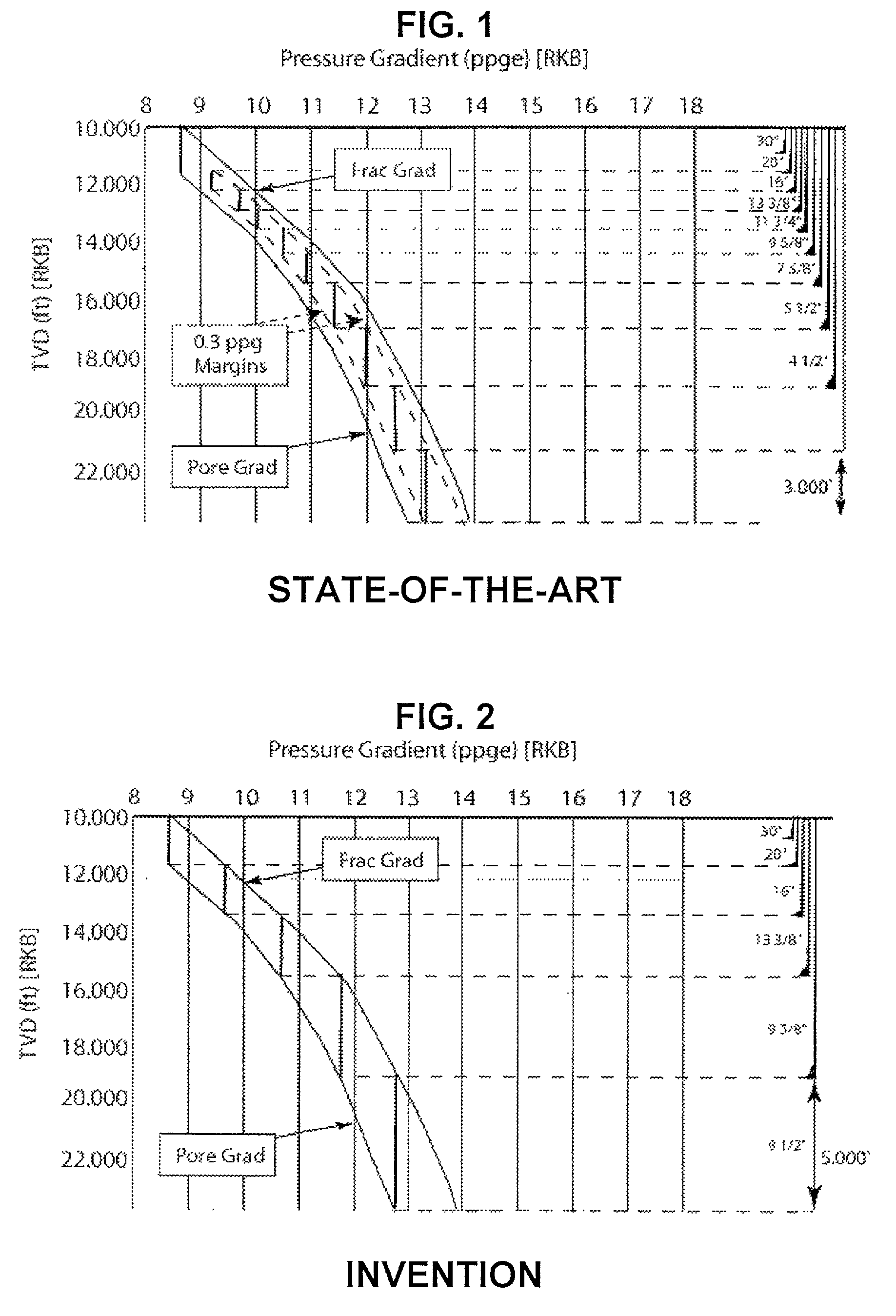
From FIG. 1, it can be seen that the last phase of the well can only have a maximum length of 3,000 ft, since the
mud weight at this point starts to fracture the rock, causing mud losses.
It is not difficult to imagine the problems created by drilling in a narrow margin, with the requirement of several casing strings, increasing tremendously the cost of the well.
Moreover, the current well design shown in FIG. 1 does not allow to reach the total depth required, since the bit size is continuously reduced to install the several casing strings needed.
In most of these wells, drilling is interrupted to check if the well is flowing, and frequent mud losses are also encountered.
In many cases wells need to be abandoned, leaving the operators with huge losses.
These problems are further compounded and complicated by the density variations caused by temperature changes along the wellbore, especially in deepwater wells.
This can lead to significant problems, relative to the narrow margin, when wells are shut in to detect kicks / fluid losses.
The
cooling effect and subsequent density changes can modify the ECD due to the temperature effect on mud
viscosity, and due to the density increase leading to further complications on resuming circulation.
Thus using the conventional method for wells in ultra
deep water is rapidly reaching technical limits.
The industry has mainly taken the direction of the second alternative, due to arguments that
well control and understanding of two-phase flow complicates the whole drilling operation with gas injection.
However, there are several technical issues to be overcome with this option, which will
delay field application for some years.
The cost of such systems is also another negative aspect.
Potential problems with
subsea equipment will make any repair or problem turn into a long down-time for the rig, increasing even further the cost of exploration.
These methods have limited application, i.e., underbalanced and air drilling are limited to formations with stable wellbores, and there are significant equipment and procedural limitations in handling produced
effluent from the wellbore.
The underbalanced method is used for limited sections of the wellbore, typically the reservoir section.
This limited application makes it a specialist alternative to conventional drilling under the right conditions and design criteria.
Air drilling is limited to dry formations due to its limited capability to
handle fluid influxes.
Similarly Mud-Cap drilling is limited to specific reservoir sections (typically highly fractured vugular carbonates).
This is in contrast to known open well methods which require pausing
fluid injection and drilling to unload excess fluid, and add additional fluid, by
trial and error until pressure is restored, which can take a matter of hours of
fluid circulation to restore levels.
This leads to significant time savings as the traditional approach to dealing with influxes is very time-consuming: stopping drilling, shutting in the well, observing, measuring pressures, circulating out the influx by the accepted methods, and adjusting the
mud weight.
Similarly a loss of
drilling fluid to the formation leads to analogous series of time-consuming events.


