Fuel injection control apparatus and method of direct fuel injection-type spark ignition engine
a technology of direct fuel injection and control apparatus, which is applied in the direction of electric control, combustion air/fuel air treatment, speed sensing governor, etc., can solve the problems of inability to purge, the state of combustion in the engine may deteriorate in some cases, and the change of air-fuel ratio (decreased)
- Summary
- Abstract
- Description
- Claims
- Application Information
AI Technical Summary
Benefits of technology
Problems solved by technology
Method used
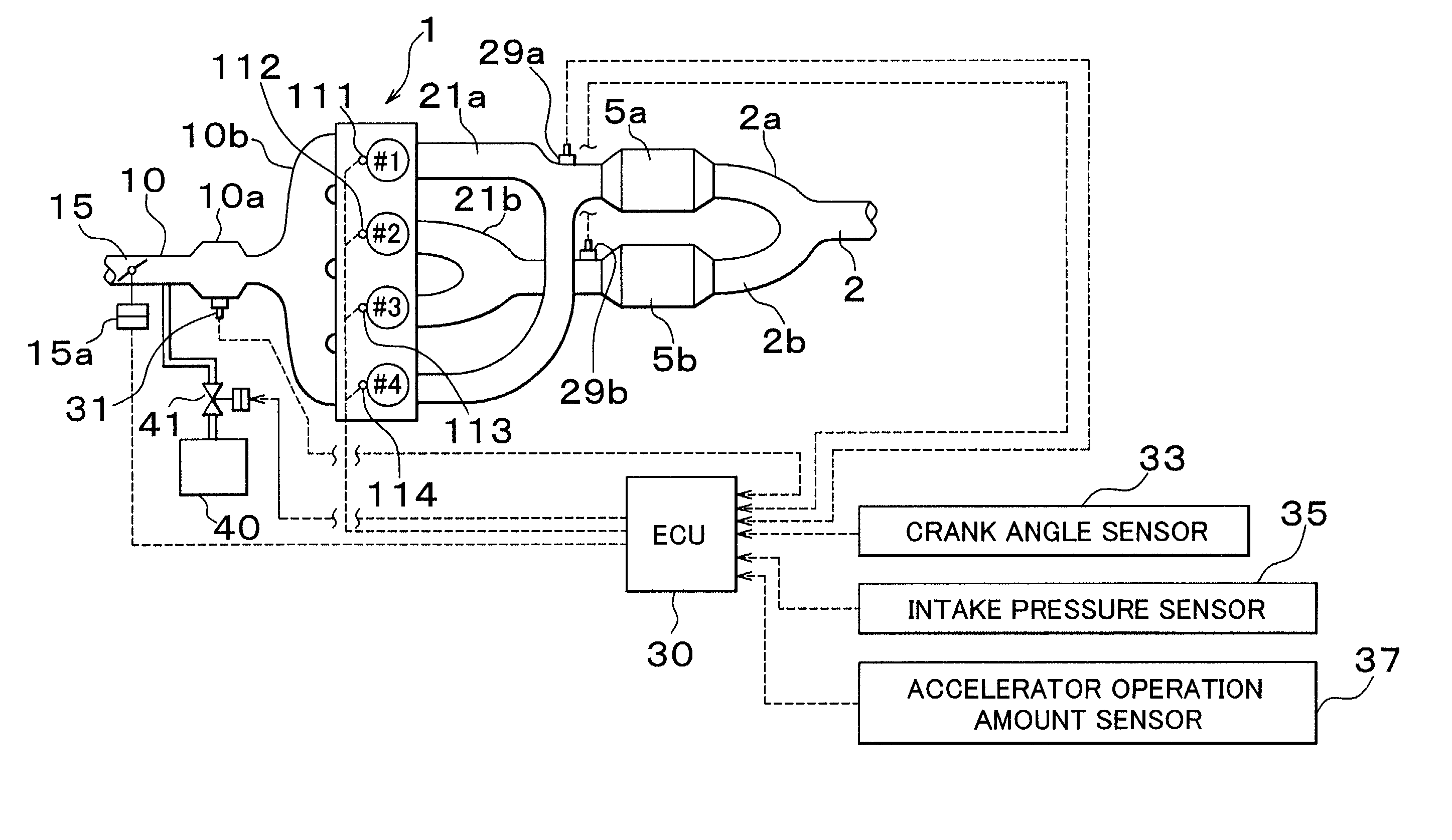
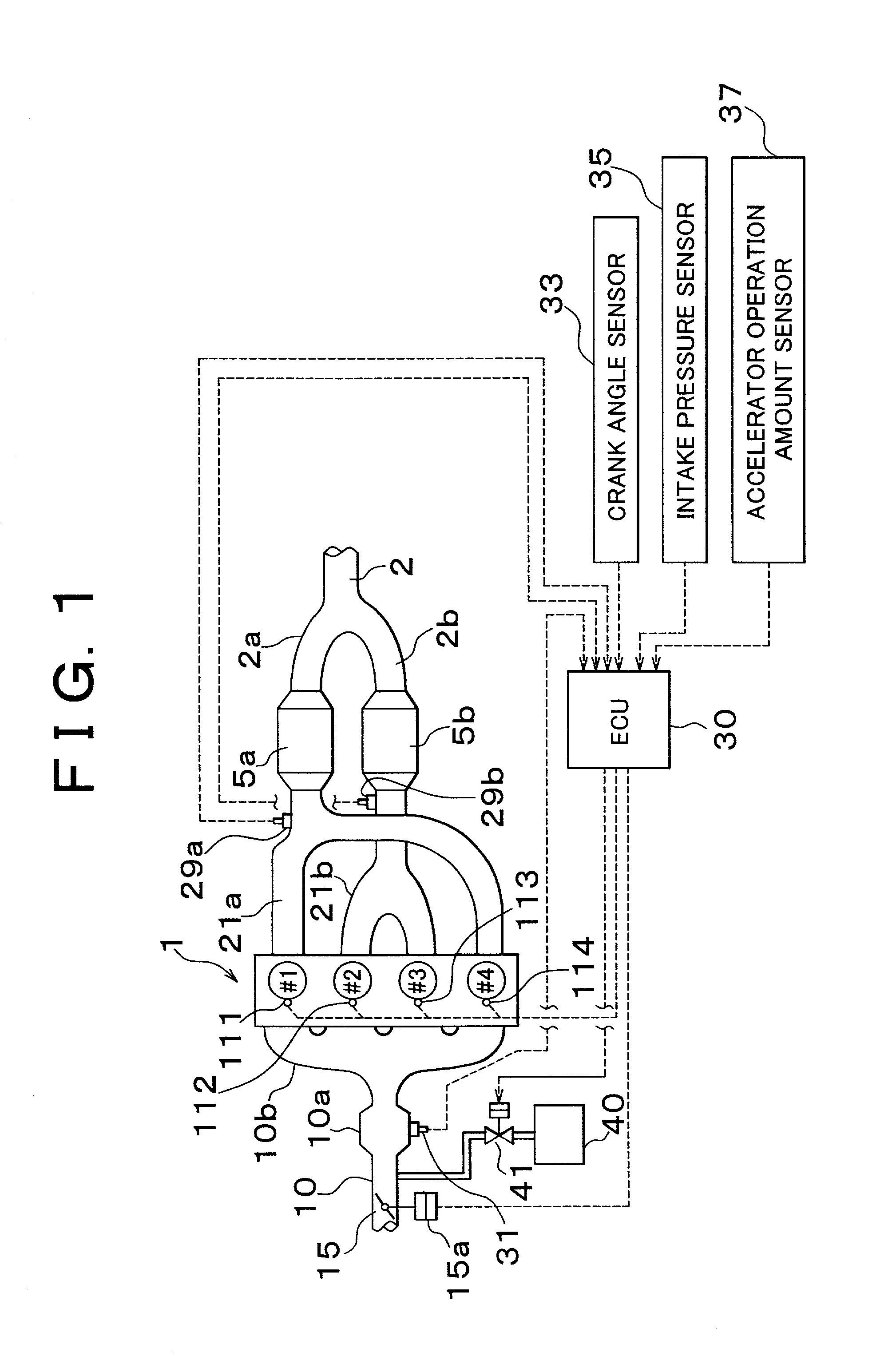
Image

Examples
second embodiment
[0114] 2) SECOND EMBODIMENT
[0115] In the first embodiment, the amount .beta. of retardation of the start of fuel injection is directly calculated from the correction factors KNE1 and KKL1. The second embodiment differs from the first embodiment in that a fuel injection start delay time (millisecond) is calculated from the vapor-corresponding value B, and the calculated delay time is converted into a retardation amount .beta. (crank angle). Therefore, the second embodiment makes it possible to set a fuel injection starting timing more precisely.
[0116] FIG. 7 is a flowchart illustrating a fuel injection control operation in accordance with this embodiment. This operation is performed as a routine that is executed by the ECU 30 at every predetermined crank rotation angle.
[0117] In steps 701 to 709 in FIG. 7, a corrected sensor output ratio A, a vapor-corresponding value B and a base fuel injection starting timing INJT are calculated as in the operation illustrated in FIG. 3. The operat...
third embodiment
[0127] 1) THIRD EMBODIMENT
[0128] FIG. 8 is a flowchart illustrating a fuel injection control operation performed during the stratified charge combustion operation. This control operation is executed by the ECU 30 at every predetermined crank angle rotation.
[0129] In this embodiment, a fuel injection control is performed with reference to the fuel injection ending timing. The calculation of the amount of fuel injection and the amount of advancement of the fuel injection ending timing is based on substantially the same concept as in the second embodiment described above in conjunction with the homogeneous mixture combustion.
[0130] In step 801 in FIG. 8, it is determined whether the engine is presently operated in the stratified charge combustion mode. A compression stroke fuel injection control of steps 803 to 823 is performed only if the engine is presently operated in the stratified charge combustion mode. If it is determined in step 801 that the engine is not presently operated in ...
fourth embodiment
[0137] 2) FOURTH EMBODIMENT
[0138] FIG. 9 is a flowchart illustrating a compression stroke fuel injection control that is different from the control operation of the third embodiment.
[0139] The operation illustrated in the flowchart in FIG. 9 is substantially the same as the operation illustrated in FIG. 8, except that in step 921, an actual fuel injection amount TAU2 is set as in TAU2=TAU.
[0140] That is, in this embodiment, the amount of fuel injection is not reduced for correction at the time of execution of the purging whereas the fuel injection ending timing is corrected in accordance with the amount of fuel vapor. In this embodiment, the fuel injection duration remains the same as the base fuel injection duration, and therefore, the fuel injection is advanced as a whole. As a result, injected fuel readily diffuses in each cylinder, so that the rich-side deviation of the air-fuel ratio of stratified mixture can be prevented without a need to correct the amount of fuel injection i...
PUM
 Abstract
Description
Claims
Application Information
 - R&D
- Intellectual Property
- Life Sciences
- Materials
- Tech Scout
- Unparalleled Data Quality
- Higher Quality Content
- 60% Fewer Hallucinations
Browse by: Latest US Patents, China's latest patents, Technical Efficacy Thesaurus, Application Domain, Technology Topic, Popular Technical Reports.
© 2025 PatSnap. All rights reserved.Legal|Privacy policy|Modern Slavery Act Transparency Statement|Sitemap|About US| Contact US: help@patsnap.com