
Catalyst carrier holding member, method of making the same and catalyst converter

a technology of catalyst converter and carrier, which is applied in the direction of physical/chemical process catalyst, organic compound/hydride/coordination complex catalyst, separation process, etc., can solve the problems of limited applicability of mat, low yield, and difficulty in automation

Inactive Publication Date: 2002-02-28
NICHIAS CORP
View PDF3 Cites 53 Cited by
  • Summary
  • Abstract
  • Description
  • Claims
  • Application Information

AI Technical Summary

Benefits of technology

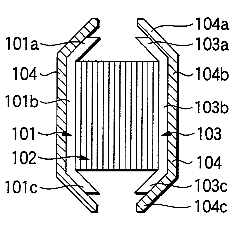
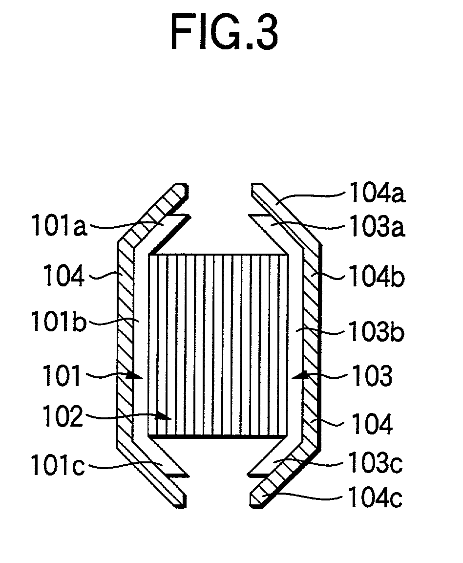
[0012] As a result of extensive studies, the present inventors made an inorganic fiber molding comprising a three-dimensional molded article including flexible inorganic fiber and an inorganic expansive admixture, if desired, wherein the flexible inorganic fiber is bound together by a binder in a compression-deflected state. Further, a surface in contact with the catalyst carrier is shaped substantially in conformity to the outer shape of the catalyst carrier, and a surface in contact with the casing is substantially in conformity to the inner shape of the casing, and the catalyst carrier holding member has a thickness equal to or larger than the gap. They have ascertained that the catalyst carrier holding member having the above structure is applicable even to a complicated shape to give a good fit to a catalyst carrier or a casing without scatter in assembly finish thereby keeping holding properties stably for a long period of time. The ease of fitting makes it feasible to automate the assembly operation, which leads to cost reduction. Since the catalyst carrier holding member contains no or a reduced amount of an organic binder, contamination of an exhaust gas with the vaporized or burnt organic binder can be avoided or suppressed. The present invention has been completed based on these findings.

Problems solved by technology

Since the assembly operation is carried out by hand, the finish tends to vary among products, and the yield is low due to fitting failure.
Because the series of assembly operation should be done with delicacy, automation is difficult, which has been a bar to cost reduction.
The mat has limited applicability because of its flat shape.
When a casing or a catalyst carrier has a complicated shape, for example, when a casing has a tapered or curved section, or when a catalyst carrier has a neck portion, the mat is liable to come in non-uniform contact or fail to contact in parts with the catalyst carrier or the casing, resulting in a failure to hold the catalyst carrier sufficiently.
The mat has another problem that an inner layer and an outer layer of the inorganic fiber shaped article tend to separate from each other in long-term use due to vibrations, etc., resulting in a reduction of catalyst carrier holding properties.
As a result, the outer layer containing an inorganic expansive admixture, which has poor heat resistance, is readier to deteriorate than the inner layer, which accelerates the layer separation.
Fibers shorter than 10 .mu.m have insufficient flexibility, tending to result in insufficient cushioning properties.
A fiber length greater than 100 mm tends to result in too high a repulsive force, i.e., a force of recovery from deflection when the catalyst carrier holding member is used.
An amount less than 1 part results in insufficient binding of the fibers.
An organic binder is lost to some extent through vaporization or burning by the heat during use of the catalyst converter.
An amount less than 1 part results in insufficient binding of the fibers.
Out of these ranges, the above-mentioned disadvantages result.
As a result, the multilayer structure hardly undergoes layer separation and resultant positional deviation during use.
In this embodiment, the catalyst carrier holding member hardly undergoes layer separation and resultant positional deviation during use.

Method used


Image

  • Catalyst carrier holding member, method of making the same and catalyst converter
  • Catalyst carrier holding member, method of making the same and catalyst converter
  • Catalyst carrier holding member, method of making the same and catalyst converter

Examples


Embodiment Construction

[0057] The present invention will now be illustrated in greater detail with reference to Example, but it should be understood that the invention is not construed as being limited thereto.

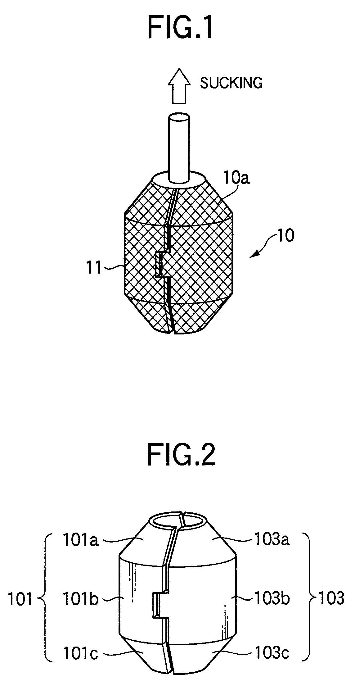
[0058] A suction-dewatering mold 10 shown in FIG. 1 was prepared. The mold 10 has a wire net 10a shaped in conformity to the contour of a catalyst carrier and having fins 11 1sticking out from its outer surface to make slits in an angular U-shape. The mold 10 exerts suction from the outside toward the inside through the wire net 10a.

[0059] Alumina fiber (97 parts) having an Al.sub.2O.sub.3 content of 72% and an SiO.sub.2 content of 28%, of which fiber length is 3 mm and a fiber diameter is 3 .mu.m, and 3 parts of latex were mixed in water, and 0.1 part of a nonionic flocculant was added thereto to prepare a slurry having a solid content of 2%.

[0060] The dewatering mold 10 was immersed in the slurry, and the slurry was sucked up to deposit the fiber on the mold 10 to form a preform. The mold 10 was t...


PUM

PropertyMeasurementUnit
lengthaaaaaaaaaa
diameteraaaaaaaaaa
diameteraaaaaaaaaa

Abstract

The present invention provides a catalyst carrier holding member to be fitted into a gap between a catalyst carrier and a casing accommodating the catalyst carrier. The catalyst carrier holding member includes a three-dimensional molded article having flexible inorganic fiber and an inorganic expansive admixture, if desired. The flexible inorganic fiber is bound together by a binder in a compression-deflected state. A surface in contact with the catalyst carrier is shaped substantially in conformity to the outer shape of the catalyst carrier, and a surface in contact with the casing is substantially in conformity to the inner shape of the casing. The catalyst carrier holding member has a thickness equal to or larger than the gap.

Description

[0001] 1. Field of the Invention[0002] This invention relates to a catalyst carrier holding member used in a catalyst converter for purifying exhaust gases from internal combustion engines, e.g., of automobiles, a method of making the catalyst carrier holding member, and a catalyst converter having the catalyst carrier holding member.[0003] 2. Description of the Related Art[0004] A catalyst converter is composed mainly of a catalyst carrier for supporting a catalyst for purifying exhaust gases, such as a honeycomb structure or porous ceramics, a casing for holding the catalyst carrier, and a catalyst carrier holding member which is fitted between the catalyst carrier and the casing to hold the catalyst carrier. The catalyst converter is further composed of a sealing member, etc.[0005] The catalyst carrier holding member is required to have holding properties for fitting in the space without leaving a gap thereby to hold the catalyst carrier securely, cushioning properties for protec...

Claims


Application Information

Patent Timeline
Patent Type & Authority Applications(United States)
IPC IPC(8): B01D53/86B01J33/00B01J35/06F01N3/28
CPCF01N3/2853F01N3/2857F01N3/2864Y10T428/249924F01N3/28
Inventor GOTO, YOSHIHIKOANJI, TOSHIYUKIKAWASAKI, YOSHIHIROONOUE, TAKASHINIWA, TAKAHIROTANAKA, MASAFUMIYONEZAWA, SYOUICHI
Owner NICHIAS CORP
Learn More