
Optical amplifier and a method of preventing emission therefrom of optical power exceeding a prescribed safety limit

a technology of optical amplifier and safety limit, which is applied in the direction of fiber transmission, laser details, electrical equipment, etc., can solve the problems of difficult to satisfy, and harmful to the human eye, and reducing the gain of the active fiber

Inactive Publication Date: 2001-11-01
CORIANT
View PDF0 Cites 0 Cited by
  • Summary
  • Abstract
  • Description
  • Claims
  • Application Information

AI Technical Summary

Benefits of technology

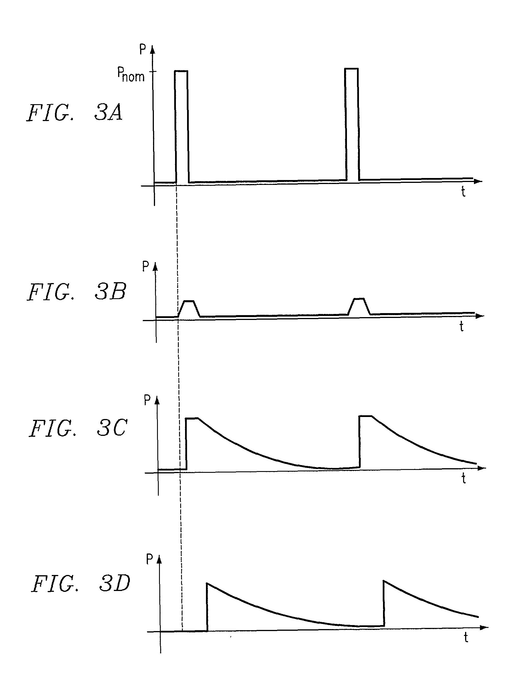
[0016] Pulsing of the pump power ensures that its mean power can be kept so low in the safety state that the emitted light is unharmful to the human eye, while the instantaneous power of the pulses is sufficiently high for the active fiber to respond on reception of these pulses and to inform the pump unit--via the pump fiber or optionally another existing fiber--that the pump fiber is now intact again. When--and if--a pump pulse arrives at the active fiber, the optical power contained in the pulse will be absorbed by the active fiber which, in response to the pulse, simultaneously generates a spontaneous noise called ASE (Amplified Spontaneous Emission), and this ASE signal may then be returned to the pump unit.
[0027] Finally, the pump unit may be adapted to inhibit the detection of whether an optical signal in response to the pulsed pump power is returned from the active fiber, until a selected period of time has elapsed after the transmission of each pulse from the pump unit. This ensures that the detector circuit ignores the reflections that will be returned from the pump fiber, irrespective of whether this is intact or broken, and instead exclusively detects the ASE noise which can only originate from the active fiber, and which will last considerably longer than the reflections from the pump fiber.
[0028] As mentioned, the invention also relates to a method of preventing emission of optical power exceeding a prescribed safety limit on interruption of an optical fiber which transfers pump power from a pump unit to an active fiber. When the mean power of the pump power is changed in response to a signal received from the active fiber such that the mean power assumes a value below said safety limit if said signal is not received, and assumes a nominal value if said signal is received, it is ensured that the mean power may automatically be reduced to a safe level when a break occurs on the optical fiber.

Problems solved by technology

The light transmitted in such fibers, in the form of communications signals or pump power, is typically harmful to the human eye.
It is the temporal mean power of the light that is harmful to the eye.
For remote-pumped amplifiers, such as e.g. RILP, this requirement, however, is not easy to satisfy, as the reduced pump power results in a considerable reduction in the gain of the active fiber.
Therefore, the communications signals arriving at the receiver after the re-establishment of the transmission path, will frequently be below the sensitivity limit of the receiver because of the reduced pump power.
Although this solution is technically adequate, it is vitiated by the serious drawback that it requires an additional fiber typically of a length of 10-50 km.
However, this can only be done if there is an extra fiber or another transmission channel for transfer of the alarm signal and, therefore, this system also has the above-mentioned drawback.
Further, the system is not suitable for reducing pump power, unless a special detector unit as above is provided at the active fiber for generation of an alarm signal.

Method used


Image

  • Optical amplifier and a method of preventing emission therefrom of optical power exceeding a prescribed safety limit
  • Optical amplifier and a method of preventing emission therefrom of optical power exceeding a prescribed safety limit

Examples


Embodiment Construction

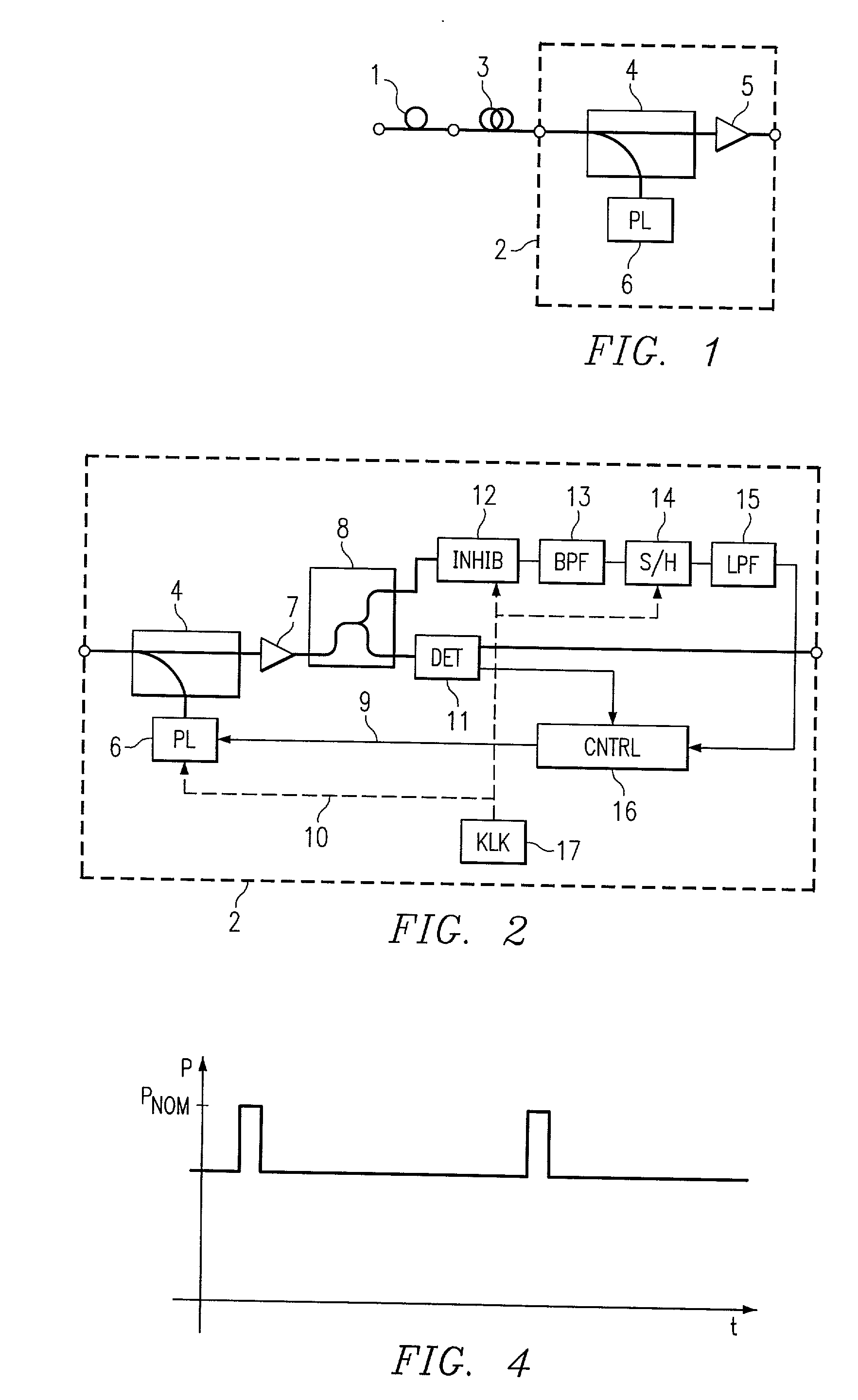
[0035] FIG. 1 shows an example of an optical remote-pumped amplifier of the invention. The example involves an optical preamplifier consisting of an erbium-doped fiber 1 and a receiver and pump unit 2 connected to the erbium-doped fiber by a transmission and pump fiber 3, which may typically have a length of 10-50 km.

[0036] In the receiver and pump unit 2, the light arriving from the fiber 3 passes via a wavelength multiplexer 4 to a receiver or amplifier circuit 5, in which the transmission or information signals contained in the light may be received and optionally be passed on for further processing. A pump laser 6 generates optical pump power which is transmitted via the wavelength multiplexer 4 out on the fiber 3 in a direction toward the erbium-doped fiber 1. Typically, the light with the information signals may have a wavelength of 1550 nm, while oppositely directed pump light may have a wavelength of 1480 nm, thereby enabling the wavelength multiplexer 4 to transmit the info...


PUM


Abstract

An optical amplifier comprises an active fiber (1), a pump unit (2) spaced from the active fiber and adapted to give a nominal, continuous pump power in an operational state, and a pump fiber (3) adapted to transfer optical pump power from the pump unit (2) to the active fiber (1). Moreover, in a safety state, the pump unit (2) is adapted to give a pulsed pump power whose mean power is lower than a prescribed safety limit. A method of preventing emission of optical power exceeding a prescribed safety limit on interruption of an optical fiber (3) which transfers pump power from a pump unit (2) to an active fiber (1), comprises changing the mean power of the pump power in response to a signal received from the active fiber (1) so that the mean power assumes a value below said safety limit if said signal is not received, and assumes a nominal value if said signal is received.

Description

RELATED APPLICATION[0001] This application is a continuation of U.S. Ser. No. 09 / 308,342 filed Nov. 14, 1997 now U.S. Pat. No. ______, which claims the priority of PCT / DK97 / 00518 filed Nov. 14, 1997.TECHNICAL FIELD OF THE INVENTION[0002] The invention relates to an optical amplifier comprising an active fiber, a pump unit spaced from the active fiber and adapted to give a nominal, continuous pump power in an operational state, and a pump fiber adapted to transfer pump power from the pump unit to the active fiber.[0003] The invention moreover relates to a method of preventing emission of optical power exceeding a prescribed safety limit upon interruption of an optical fiber which transfers pump power from a pump unit to an active fiber.BACKGROUND OF THE INVENTION[0004] Optical fiber amplifiers for amplifying optical signals typically consist of a length of active fiber, which may e.g. be an erbium-doped fiber, and a unit for generating pump power, e.g. a pump laser. When the active f...

Claims


Application Information

Patent Timeline
Patent Type & Authority Applications(United States)
IPC IPC(8): H01S3/00
CPCH01S3/00H04B2210/08H04B10/2931
Inventor PEDERSEN, CLAUS F.NIELSEN, SOREN M.
Owner CORIANT
Learn More