
Dust sensing assembly air intake system

a technology of air intake system and dust sensing assembly, which is applied in the direction of intake silencers for fuel, air cleaner and silencer combination, combustion-air/fuel-air treatment, etc., can solve the problems of poor performance, improper installation of air filters, and propagation of engine nois

Inactive Publication Date: 2001-11-01
SIEMENS CANADA LTD
View PDF0 Cites 18 Cited by
  • Summary
  • Abstract
  • Description
  • Claims
  • Application Information

AI Technical Summary

Benefits of technology

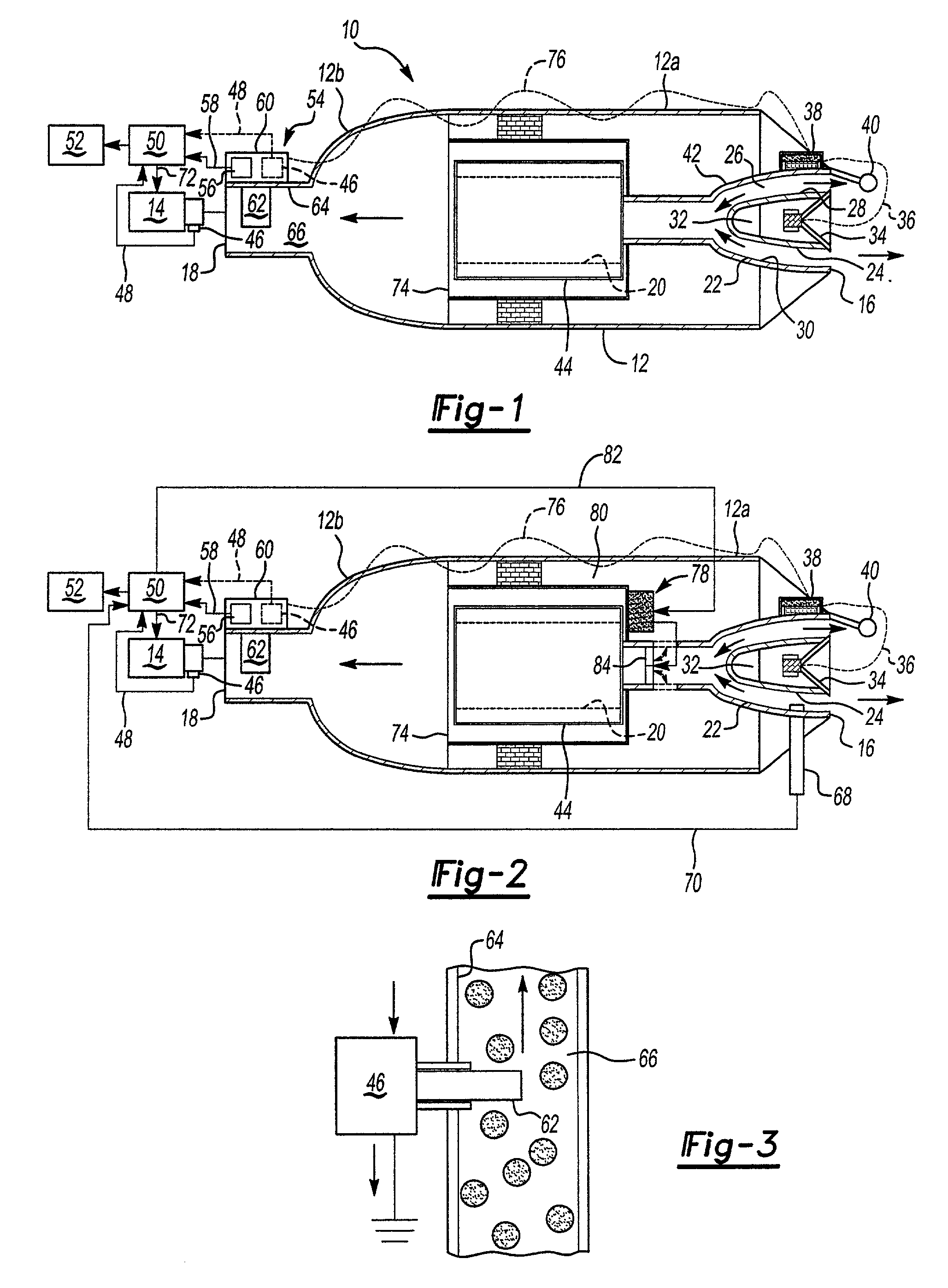
[0009] An air intake or induction system includes a particulate sensor that sends a particulate signal representative of the particulate concentration entering a vehicle engine to an output device monitored by a vehicle operator. If particulate concentration levels are higher, the signal can alert the operator that the filter is improperly installed, the filter has a hole or other damage, or that the clean air hose has been disconnected. These early detections allow the operator to correct the problems when they occur, thus reducing engine wear.
[0014] The subject apparatus provides a simple method for monitoring dust and dirt particulate concentration levels that are entering a vehicle engine. This results in reduced engine wear and can extend filter life when the by-pass mechanism is utilized.

Problems solved by technology

Engine noise is propagated through the air induction systems, which is undesirable.
Often, the air that is drawn into the system through the air duct housing includes dust, dirt, and other particulate contaminants.
These contaminants can clog the engine resulting in poor performance.
Sometimes the air filter is not properly installed or becomes damaged during vehicle operation, which allows the contaminants to enter the engine.
One disadvantage with air filters is that the system experiences a pressure drop as the air is drawn through the filter.
If particulate concentration levels are higher, the signal can alert the operator that the filter is improperly installed, the filter has a hole or other damage, or that the clean air hose has been disconnected.
This results in reduced engine wear and can extend filter life when the by-pass mechanism is utilized.

Method used


Image

  • Dust sensing assembly air intake system

Examples


Embodiment Construction

[0019] Referring to the drawings, FIG. 1 shows an air intake or induction system 10 including an air intake housing 12 forming part of noise attenuation assembly. The air induction system 10 provides air to an internal combustion engine 14. The air intake housing 12 has an inlet 16 and an outlet 18 and an airflow passageway 20 that extends between the inlet and the outlet.

[0020] Mounted within the air intake housing 12 is a speaker housing 22 and a mid-body portion 24 is mounted within the speaker housing 22. The mid-body portion 24 is concentrically positioned within speaker housing 22 on a pair of integrally formed struts (not shown) to define an annular passage 26 between an exterior surface 28 of the mid-body portion 20 and an interior surface 30 of the speaker housing 12. The mid-body portion 20 is preferably parabola shaped to define a central chamber 32 with a tapered bottom end facing the engine 14 and an open end facing away from the engine 14.

[0021] A speaker assembly 34 i...


PUM


Abstract

An air induction system for a vehicle engine includes a sensor assembly for monitoring particulate concentration. The sensor assembly is mounted within an air intake housing, which has an inlet and an outlet. An airflow passageway extends between the inlet and the outlet to the vehicle engine. An air filter is mounted within the housing to filter particulates from air flowing through the airflow passageway. The sensor assembly can be mounted to an intake manifold or incorporated into a mass airflow sensor. The particulate sensor generates a particulate signal representative of particulate concentration entering the vehicle engine via the outlet. The signal is sent to an output device monitored by a vehicle operator.

Description

[0001] This application claims priority to provisional applications No. 60 / 193,225 filed on Mar. 30, 2000 and No. 60 / 269,083 filed on Feb. 15, 2001.[0002] 1. Field of the Invention[0003] This invention relates to an integrated dust sensing assembly for a vehicle air intake system. Specifically, a dust sensor is mounted to an intake manifold or integrated into a mass air flow sensor unit to monitor the dust intake to an engine.[0004] 2. Related Art[0005] Internal combustion engines include air induction systems for conducting air to the engine. Engine noise is propagated through the air induction systems, which is undesirable. Noise attenuation mechanisms have been installed within the air induction systems to reduce these noises. Typically these noise attenuation mechanisms include a speaker, a sound detector, a signal generator, and various other components that are used to reduce noise generated by the air induction system. These components are mounted within an air duct housing.[...

Claims


Application Information

Patent Timeline
IPC IPC(8): F02M35/04F02M35/12F02M35/14
CPCF02M35/021F02M35/08F02M35/10393F02M35/14F02M35/125
Inventor DALY, PAUL D.VANDERVEEN, JAMES K.
Owner SIEMENS CANADA LTD
Learn More