
Print liquid tank and printing apparatus having the same

a technology of printing apparatus and liquid tank, which is applied in the direction of printing and other printing apparatus, etc., can solve the problems of increasing the steps of assembly process, not being practical, and only being able to indicate the remaining amount of ink, etc., and not being able to feed back to the printer body

Inactive Publication Date: 2001-10-25
CANON KK
View PDF0 Cites 70 Cited by
  • Summary
  • Abstract
  • Description
  • Claims
  • Application Information

AI Technical Summary

Problems solved by technology

While many technologies have been proposed publicly which concern the ink storage bag and system which measure the amount of ink remaining in the ink storage bag, but, they are mostly not put to practical use or, if adopted, only for a short period of time.
Among the reasons for this are a problem of a precision at which the remaining amount of ink is detected, a problem of increased steps in the assembly process, a problem that the remaining amount of ink can only be indicated but cannot be fed back to the printer body, and a problem of requiring a generous cost increase for implementing the feedback.
That is, it has a drawback of being unable to detect a change in the ink consumption and also a drawback of requiring a mechanism for generating light and a device for detecting the amount of light transmitted and converting the detected light output into a digital value or electric signal.
Particularly in the systems that detect changes in the electrostatic capacitance and magnetism, these changes are inversely with the square of the distance, which is disadvantageous to the detection of the remaining mount of ink.
This is because an initial change is large and a change at the last stage extremely small, making it difficult to detect a final point in the amount of remaining ink (minimum amount of remaining ink), the most critical information.
Further, the arrangement of the ink consumption detection unit 6 at the side of the ink bag 4 increases an idle space within the case 2, deteriorating the accommodation efficiency of the case 2.
If such a spring member is provided, the ink residual amount detection of this system cannot be realized with good reproducibility without using a joint portion that can withstand the inner pressure produced by the urging force of the spring member.
When such systems are not provided, shifts or variations in the position and angle of the surface of the ink storage bag cannot be corrected, making it impossible to reliably measure the change in the amount of remaining ink, though it may be possible to detect the presence or absence of ink.
When only 5 g of ink remains in the ink tank, the print task under consideration cannot be completed.
This problem can occur with the method that detects only the presence / absence of ink.
The printers are not always attended by an operator and thus when a necessary signal is to be transferred through a network or online transmission to a remote location (as by facsimile), it's self-evident that simply displaying the amount of ink used (remaining amount) cannot cope with the event described above.
If the ink bag filled with ink is 1 cm or more in thickness, the ink is likely to leak.
Below the print head there is generally a printing medium such as paper, which makes it impossible to install the ink bag beneath the ink jet print head.
This system therefore is practically not usable.
It has been found that because the ink bag is soft, the conductive member cannot be put in its place easily even by placing the rigid flat plate (e.g., iron plate) on the outer circumferential surface of the ink bag.
Hence, in long-term storage or distribution tests accompanied by temperature and humidity changes, the conductive member is found unable to get cut off at a predetermined position and creep deformations cause it to get cut off before it reaches the predetermined position, which is undesirable.
It is therefore very difficult to put such a turn-off contact mechanism in place with high reliability.
Automating the assembly of the mechanism and securing a long-term reliability are also difficult to achieve.
The system has a drawback that the current flows at all times until the minimum amount of remaining ink is detected (energy loss).
In the turn-off contact system that changes the signal level from "H" to "L", if the above-described conductive member is directly used to issue a warning of the residual ink amount with a light emitting diode (LED), the turn-off contact system needs to have an inversion circuit (made up of transistors) for inverting the signal and also an adjustment resistor, thus, the structure is not only complex, the structure also increases the cost of the product.

Method used


Image

  • Print liquid tank and printing apparatus having the same
  • Print liquid tank and printing apparatus having the same
  • Print liquid tank and printing apparatus having the same

Examples


Embodiment Construction

[0062] FIG. 6 schematically shows an example of the printing apparatus having the print liquid tank according to this invention.

[0063] The example shown in FIG. 6 is, for example, an ink jet printer having a print head unit 38 that prints on a recording surface of a sheet Pa as a printing medium.

[0064] The ink jet printer IJ has as main constitutional elements a carriage member 28 reciprocally moved and carrying the print head unit 38, ink tanks 32C-32PC for supplying inks of predetermined colors or a process liquid to print heads 38HC-38HP of the print head unit 38 detailed later, and a paper feed roller unit 26 for feeding the paper Pa to a predetermined position below the print head unit 38.

[0065] The carriage member 28 is slidably supported on guide shafts 22 and 24 disposed parallel to and facing each other. The guide shafts 22 and 24 extending virtually perpendicular to the direction of arrow F or paper Pa feed direction described later are supported at their ends by side wall...


PUM


Abstract

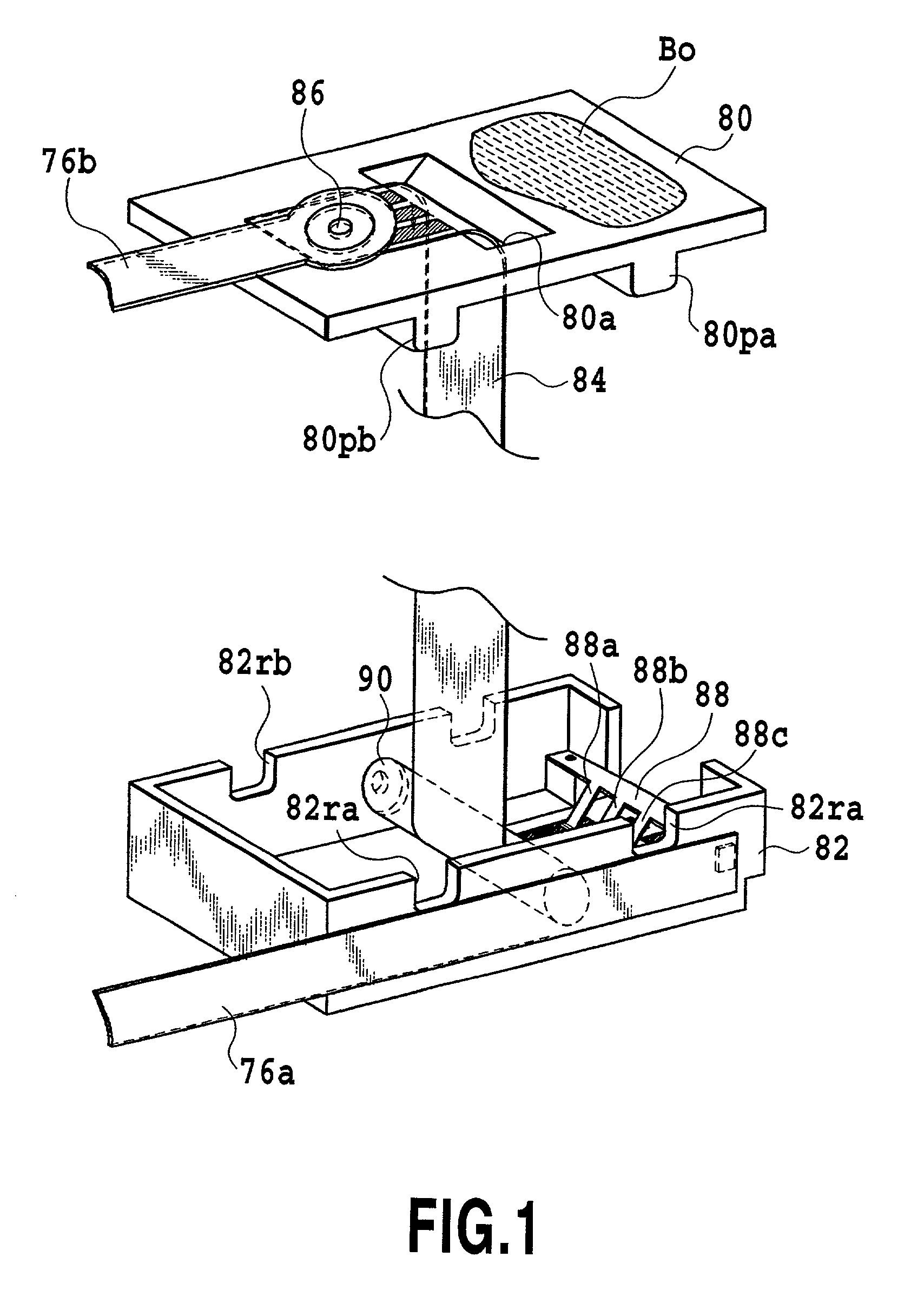
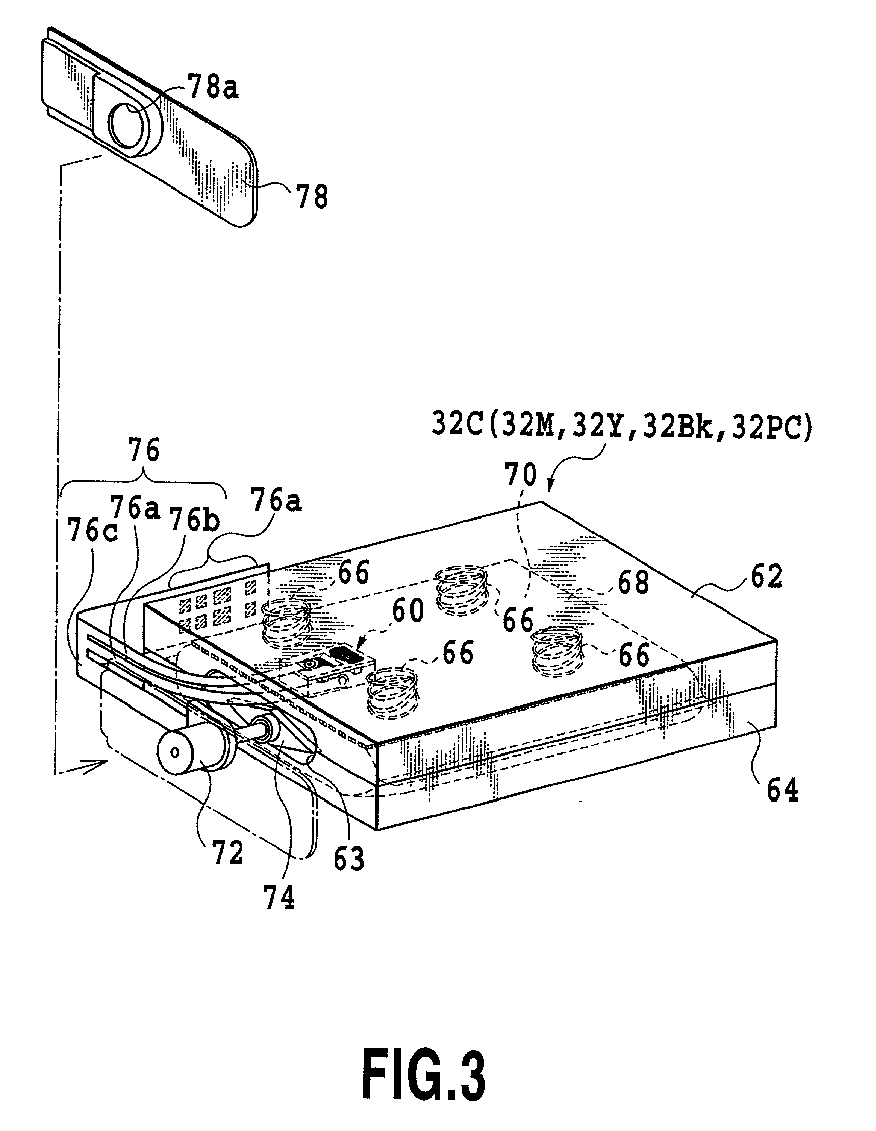
An ink consumption detection unit 60 includes the contact tape 84, whose one end is secured to the tank case 62 side and the other end to the flexible ink bag 68 side, and the contact electrode member 88 secured to the ink bag 68 side and placed in contact with the contact tape 84. As the ink in the ink bag 68 is consumed, the contact electrode member 88 is moved. When the contact electrode member 88 comes into contact with a plurality of contact electrodes 84EA, 84EB, 84EC representing ink consumptions in stages, the ink consumption detection unit 60 successively issues detection signals representing the ink consumptions.

Description

[0001] This application is based on Patent Application No. 2000-117064 filed Apr. 18, 2000 in Japan, the content of which is incorporated hereinto by reference.[0002] 1. Field of the Invention[0003] The present invention relates to a print liquid tank for supplying a print liquid to a print head that prints on a printing medium, and to a printing apparatus having the print liquid tank.[0004] 2. Description of the Related Art[0005] A continuous type large industrial printing apparatus was once a mainstream ink jet printer. An ink jet printer as a printing apparatus using an on-demand type ink jet print head came into wide use. As for an ink storage system in the ink jet print head, when a faster printing speed of the ink jet print head began to increase the ink consumption in recent years, the merits of the ink storage bag that can provide a large capacity of ink storage relatively easily, received attention. This is because, as there are growing demands for more varied kinds of prin...

Claims


Application Information

Patent Timeline
Patent Type & Authority Applications(United States)
IPC IPC(8): B41J2/175
CPCB41J2/17509B41J2/17513B41J2002/17516B41J2002/17586
Inventor EIDA, MASATAKA
Owner CANON KK
Learn More