Link-and-pin fixing structure for a crawler chain

a technology for crawler chains and fixing structures, which is applied in the direction of driving chains, couplings, manufacturing tools, etc., can solve the problems of pins being easily loose, starting or coming out, and linking chains interfering with outside obstacles

Inactive Publication Date: 2001-05-17
KOMATSU LTD
View PDF0 Cites 14 Cited by
  • Summary
  • Abstract
  • Description
  • Claims
  • Application Information

AI Technical Summary

Benefits of technology

22. According to the present invention, with the above described structure, the elastic ring is brought into the fitting space along the tapered outer-diameter face of the pin while decreasing the tightening force of the ring such that the ring contacts with the outer and inner tapered faces in the fitting space at the respective predetermined positions. Thus, the elastic ring can be fitted easily between the respective tapered faces by a relatively small pressing force.
27. That is, according to the present invention, when the external force in the axial direction is applied to the link or the pin, the force for pressing the elastic ring deeper in the fitting space is always larger than the force for pressing it out. Thus, the fitting force of the elastic ring is automatically intensified, so that the moving of the link or the pin in the axial direction can be prevented securely, whereby no looseness occurs. Thus, even if an impact in the axial direction is applied to the link or the pin, deformation, damage or the like of a lubricant-sealing member and its crush-preventing spacer disposed in a joint portion of the respective links can be prevented so that sufficient durability of the link chain is secured.
30. With such a structure, only by placing the elastic ring into the region of the tapered outer-diameter face of the pin in the fitting space, the elastic ring contacts thereto in the fitting space with an appropriate tightening force. Therefore, further to the aforementioned effects of the present invention, the elastic ring can be fixed easily and firmly between the respective tapered faces in the fitting space.
32. That is, the inside diameter of the elastic ring is set to be smaller than the outside diameter of the tapered outer-diameter face of the pin in the fitting space. Thus, if the elastic ring is fitted in the fitting space, a force directed toward the inmost of the fitting space is applied to the elastic ring by the tightening force of the elastic ring. Consequently, only by placing the elastic ring into the fitting space, the elastic ring can be set easily at an appropriate position that contacts with the tapered inner-diameter face of the link and the tapered outer-diameter face of the pin.
34. If a switching portion between the tapered outer-diameter face and the outer annular face is formed linearly at a predetermined angle, there is a possibility that a crack or the like occur at the switching portion when an external shock is applied thereto after the pins and links are fixed to the elastic ring. According to the present invention, because the switching portion is formed in a curved face so as to be dented, any possible occurrence of the crack or the like can be avoided. Furthermore, when the elastic ring is fitted in the fitting space, the ring face-contacts with part of the outer annular face curved to be dented. Thus, the fitting position of the elastic ring can be fixed. Consequently, in addition to the aforementioned function according to the present invention, a stabilized fixing function for the pin and link can be exerted.

Problems solved by technology

Therefore, the link chain interferes with outside obstacles, rocks or the like.
Additionally, end faces of the pins also tend to receive an external force or the like in their axial direction through a roller guard or the like of the vehicle body, so that the pin becomes loose easily.
If the pin is held with a small force, it may start or come out.
Thus, the lubricant-sealing member and the crush-preventing spacer of the sealing member disposed at the end portions of the links are easily deformed, starts to be displaced or damaged.
6. If the sealing member or the crush-preventing spacer of the sealing member is damaged, consumption speed of the lubricant is accelerated so that an internal abrasion occurs between the pins and the bushes to damage the pins or bushes.
As a result, the function of the link chain is lost in a short period.
That is, if the filled annular pressing-in retainer is not fitted locally between the groove surface of the pin and the inner face of the socket of the link, it is easily peeled off.
Thus, durability cannot be expected.
Further, it is necessary to adjust positions of the socket of the link and the groove in the pin accurately, which requires more equipment cost, production cost and the like, as well as strict quality control.
However, it is impossible to visually check an internal shape of the deformed and filled pressing-in retainer in the hollow portion.
Therefore, not only in assembling of the link and the pin, but also in an inspection after the assembling work, it is not possible to see whether or not the deformed pressing-in retainer is fitted securely to the wall of the hollow portion.
Thus, quality of products can not be uniform, and defective products are often produced.
If a switching portion between the tapered outer-diameter face and the outer annular face is formed linearly at a predetermined angle, there is a possibility that a crack or the like occur at the switching portion when an external shock is applied thereto after the pins and links are fixed to the elastic ring.

Method used


Image

  • Link-and-pin fixing structure for a crawler chain
  • Link-and-pin fixing structure for a crawler chain
  • Link-and-pin fixing structure for a crawler chain

Examples


Embodiment Construction

42. Hereinafter, embodiments of the present invention will be described in detail with reference to the accompanying drawings.

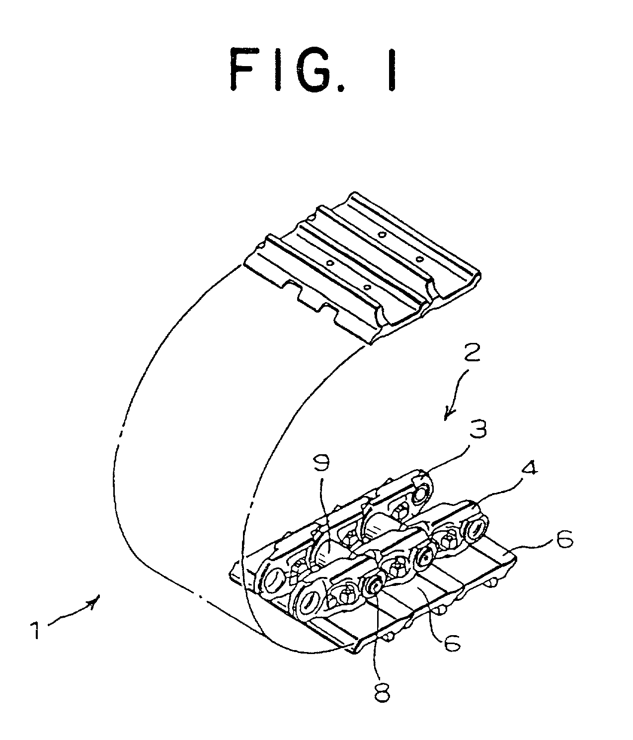
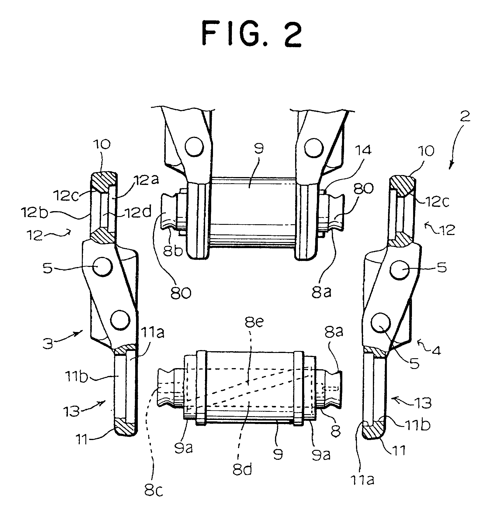
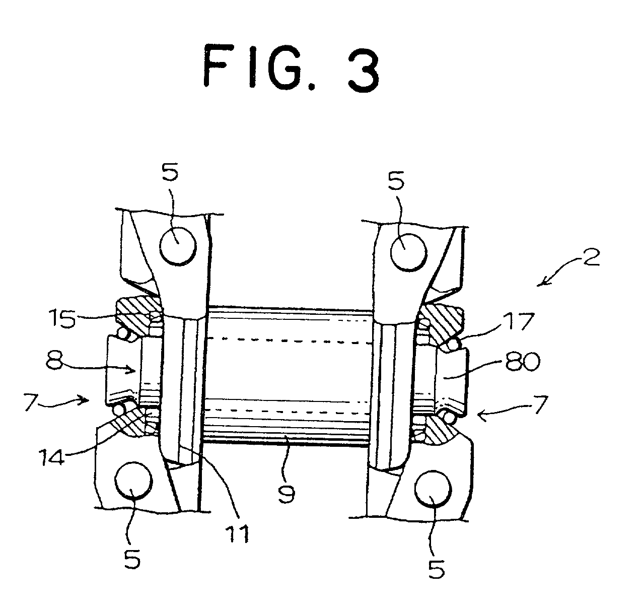
43. FIG. 1 is a structural view showing part of a link chain having a fixing structure of links and pins in the crawler chain of the present invention. FIG. 2 is a partially broken exploded view showing the link chain partially disassembled. FIG. 3 is a structural view showing a part of the link-and-pin-fixing structure, partly in cross section. FIG. 4 is a structural diagram showing contact conditions at the time when an elastic ring is fitted to the link and the pin

44. In FIG. 1, reference numeral 1 denotes a crawler chain of crawler-type vehicle for construction machine, transportation machine or the like. The crawler chain 1 is rotatably wound around traveling drive wheels (not shown) comprised of idler wheels disposed at a front part of the crawler-type vehicle, sprocket wheels disposed at a rear part thereof and track wheels disposed in a center part th...


PUM


Abstract

A fitting space having an annular opening, in which an elastic ring whose diameter of a section is D is to be fitted, is formed between a pin-press-fit hole of a link and an exposed end portion of a pin. A link inner wall face and a pin outer peripheral face in the fitting space are formed with tapered faces whose diameters decrease as they go toward an inmost of the fitting space at angles alpha and beta (alpha> beta) with respect to the axial line of the pin, respectively. The elastic ring contacts with the respective tapered faces in the fitting space at the angles alpha and beta with respect to a perpendicular passing a center of its section. Dimensions d1 and d2 between contact points at the respective tapered faces and a horizontal line passing the center of the section of the elastic ring, the diameter D of the section of the elastic ring, and the angles alpha and beta have a relation of alpha> beta, D> d1+ d2 (where d1=D / 2. cos alpha, d2= D / 2.cos beta). Therefore, the links and the pin can be connected to each other securely and firmly with a sufficient holding force to the pin in the axial direction. Thus, assembly of the links and the pin can be carried out easily at a low cost.

Description

1. 1. Field of the Invention2. The present invention relates to a structure for fixing links and pins of a traveling crawler chain to be used in a crawler-type vehicle. More particularly, it relates to a link-and-pin fixing structure for a crawler chain, which enables the links and the pins to be fixed to each other easily and firmly and in which the links and pins can be assembled securely at a low cost.3. 2. Description of the Related Art4. Plural ground-contact track shoes are mounted to an endless link chain with mounting bolts in a traveling crawler chain of a crawler-type vehicle of construction machine such as a bulldozer or a hydraulic shovel. For assembling this link chain, pins for connecting links, which are press-fitted into cylindrical bushes respectively, are press-fitted into the respective end portions of right and left links successively. The cylindrical bushes have their respective both ends exposed outside. The end portions of the respective links are coupled with...

Claims


Application Information

Patent Timeline
IPC IPC(8): B62D55/21F16B21/18
CPCB62D55/21Y10T403/583F16B2200/69
Inventor MIYAURA, SEIJI
Owner KOMATSU LTD
Why Eureka
Try Eureka