
Multilayered electrical flat conductor

An electrical connection and cable technology, applied in the field of cable connection, can solve problems such as electrical contact interference

Inactive Publication Date: 2008-01-23
AUTO KABEL MANAGEMENTGMBH
View PDF0 Cites 6 Cited by
  • Summary
  • Abstract
  • Description
  • Claims
  • Application Information

AI Technical Summary

Problems solved by technology

When using aluminum conductors, the electrical contact is disturbed due to the aluminum oxide layer on the conductor and / or on the sleeve

Method used


Image

  • Multilayered electrical flat conductor
  • Multilayered electrical flat conductor
  • Multilayered electrical flat conductor

Examples


Embodiment Construction

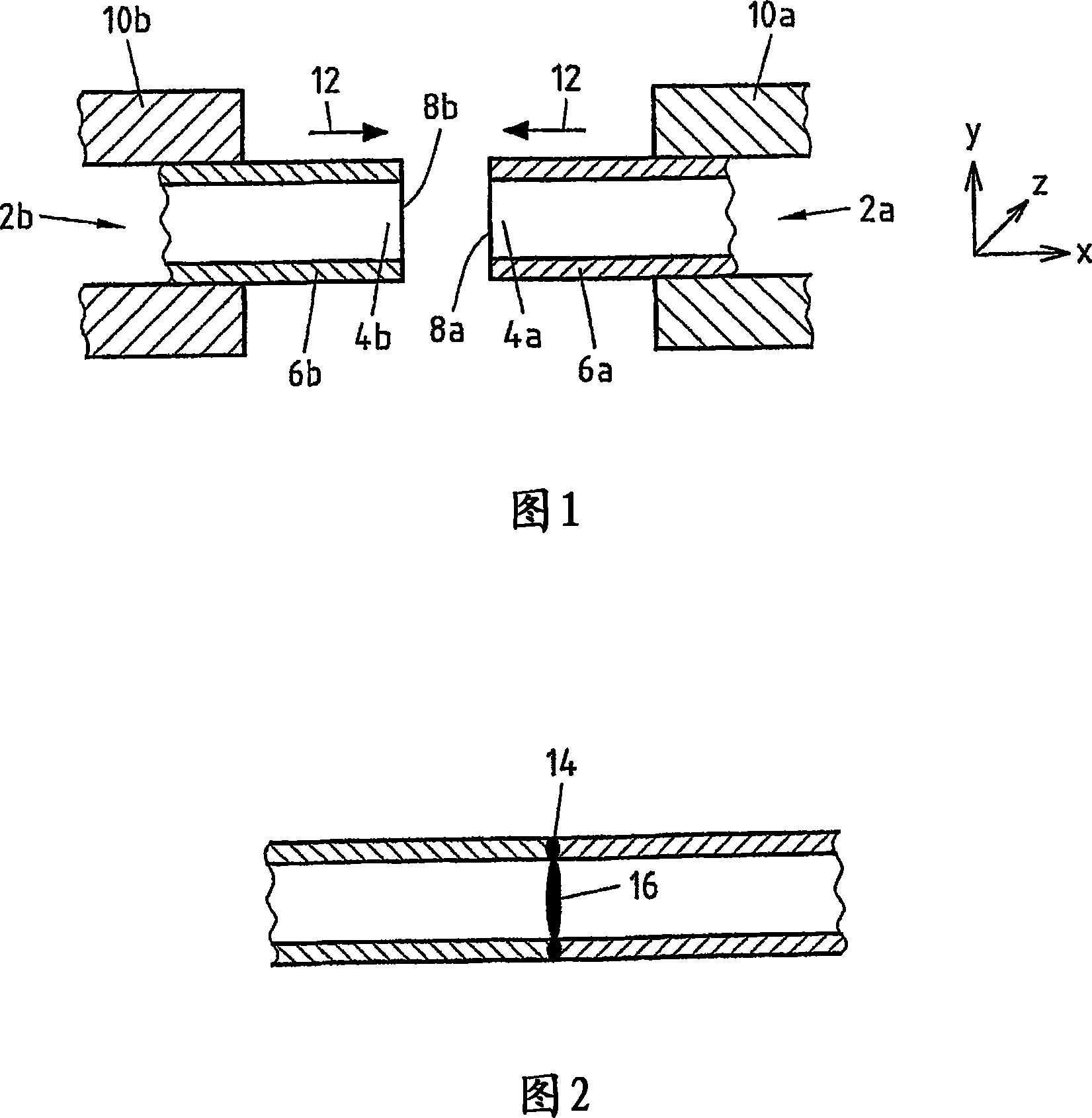
[0024] In order to realize the multi-track welding used according to the application, the workpieces to be joined must be clamped adjacent to each other on the joining surfaces in the welding tool. These joint surfaces press against each other.

[0025] For welding with the multi-track welding method, the joint surfaces are placed into oscillations, where the welding tool can be positioned in the xz-direction, yx-direction and / or yz-direction, depending on the clamping arrangement on the device oscillate in antiphase with each other. In this case the tool can oscillate with a fixed phase, phase shifted by 180°. Advantageously, the tools each oscillate only in one plane and apply the pressing force from a direction perpendicular to this plane.

[0026] With the multi-track welding method, the joining partners are materially joined to each other after less than a minute, especially after a few seconds, for example 5-7 seconds. The seam bulge is minimal because only relatively...


PUM


Abstract

The invention relates to an electric cable for motor vehicles, comprising an energy conductor which is embodied in the form of a flat conductor and surrounded by an insulating layer. In order to reduce the number of cable trees in motor vehicles, at least two other conductors are provided in the insulating layer.

Description

technical field [0001] The present patent application relates to a method for realizing an electrical connection between at least two cables, in particular battery cables for automobiles, wherein at least one first cable is formed by a wire and an insulating sheath, at least one second The cable is formed of at least one conductor. Furthermore, the present application relates to a connection between at least two cables, in particular for battery cables of a motor vehicle, wherein at least one first cable has a conductor and an insulating sheath, and at least one second cable has at least one root wire. Background technique [0002] A materially bonded fixing and connection of the cables to one another can currently be achieved, for example, by means of welding or soldering. It turns out that the friction welding method, especially the rotary friction welding method, is very suitable for connecting two cables. However, in the case of using the rotational friction welding m...

Claims


Application Information

Patent Timeline
IPC IPC(8): H02G15/24B23K20/12H01R43/02
Inventor A·默特尔
Owner AUTO KABEL MANAGEMENTGMBH
Learn More