Method for producing a cut section for a drill bit

a drill bit and cutting section technology, applied in metal sawing tool making, manufacturing tools, transportation and packaging, etc., can solve the problems of limited material choice for the ring section and the outer push element, and high production cos

Active Publication Date: 2022-11-22
HILTI AG
View PDF9 Cites 0 Cited by
  • Summary
  • Abstract
  • Description
  • Claims
  • Application Information

AI Technical Summary

Benefits of technology

[0005]An object of the present invention, in a method for producing a cutting section for a drill bit, is to reduce the manufacturing outlay for the production of the cutting section. In addition, the intention is for the functionality of the cutting section during drilling with the drill bit to be improved in respect of transmission of force, transmission of torque and / or tensile loadings during removal of a jammed drill bit.
[0016]In addition, by separation of the cutting section into the first tubular element and the second tubular element, the manufacturing outlay for producing the cutting section can be reduced. The first upper end surface forms the annular stop shoulder for transmitting force, thus obviating the need for turning. The first tubular element and the second tubular element are in the form of hollow cylinders having circular ring-shaped cross sections and have a constant material thickness.
[0018]At least one slot-shaped recess is preferably created in the second sheet metal part, wherein the at least one slot-shaped recess comprises a transverse slot and a connecting slot, and the connecting slot connects the transverse slot to the second upper end surface of the second closed tubular element. The at least one slot-shaped recess is part of the releasable connecting device which connects the cutting section to a drill shaft section of the drill bit. The slot-shaped recess is T-shaped or L-shaped and, in the connected state of the drill bit, permits a relative movement between the cutting section and the drill shaft section. The relative movement between the cutting section and the drill shaft section enables a jammed cutting section to be released from the substrate.
[0020]At least one internal depression is preferably created in the first sheet metal part, which internal depression extends over the first hollow cylinder height. The at least one internal depression in the first inner lateral surface can form a transport channel for a cooling and rinsing liquid and enables the formation of cutting sections with small internal protrusions of the drill segments on the inner side of the cutting section. The width, depth, shape and / or number of the at least one internal depression are adapted to the required quantity of cooling and rinsing liquid.
[0022]The second sheet metal part is preferably formed at the second abutting edges with at least one second positive form fitting element and at least one corresponding second negative form fitting element, wherein the at least one second positive form fitting element and the at least one second negative form fitting element are connected in a form fitting manner. The connection of the second abutting edges via second form fitting elements has the advantage that heat which may lead to stresses in the second tubular element is not admitted into the second tubular element.

Problems solved by technology

Disadvantages of the known “Hilti DD X-CM” cutting sections are the high outlay on production due to the turning of the annular stop shoulder and the milling of the slot-shaped recesses.
In addition, the choice of material for the ring section and the outer push element is limited.

Method used


Image

  • Method for producing a cut section for a drill bit
  • Method for producing a cut section for a drill bit
  • Method for producing a cut section for a drill bit

Examples


Embodiment Construction

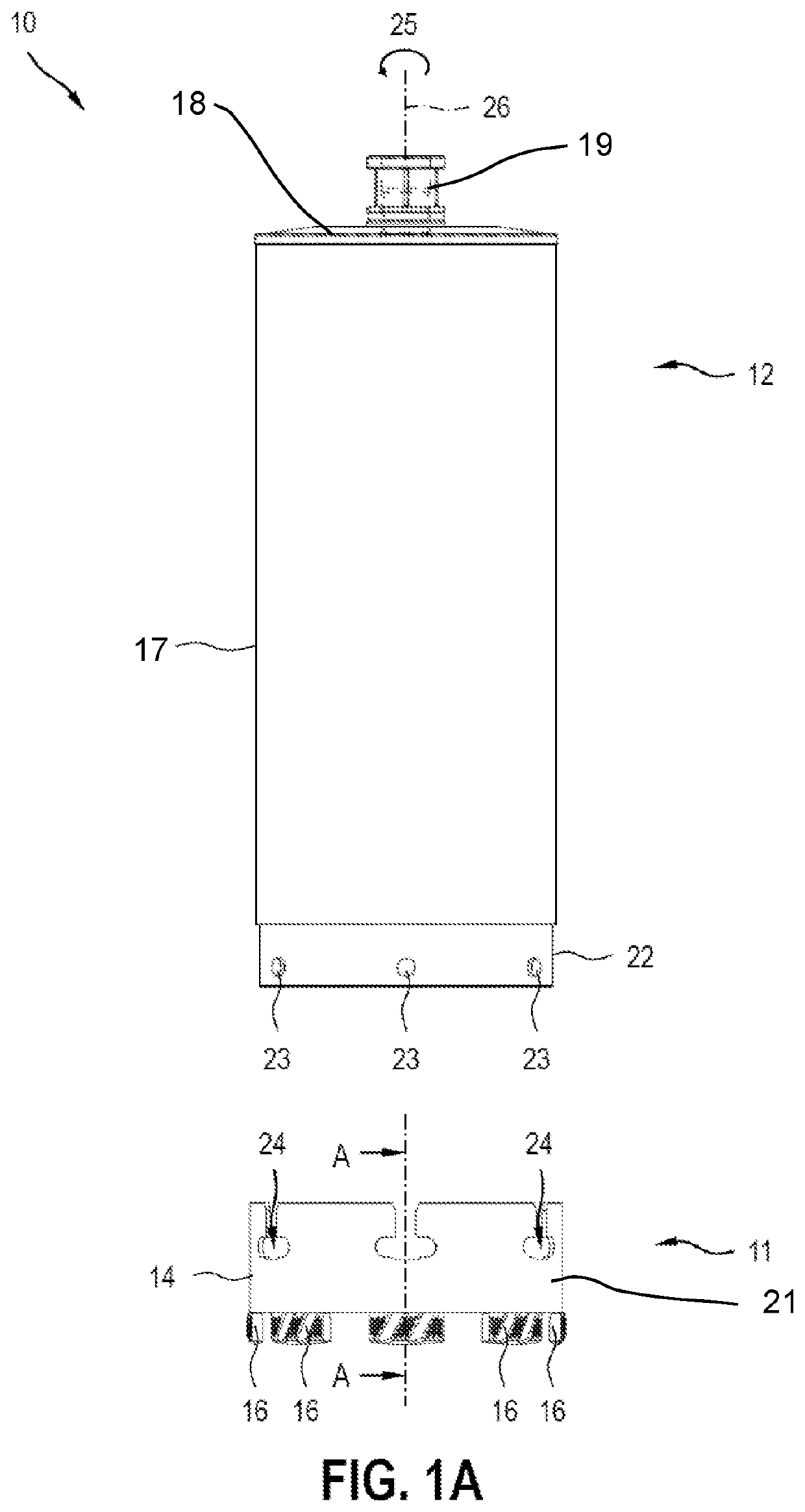
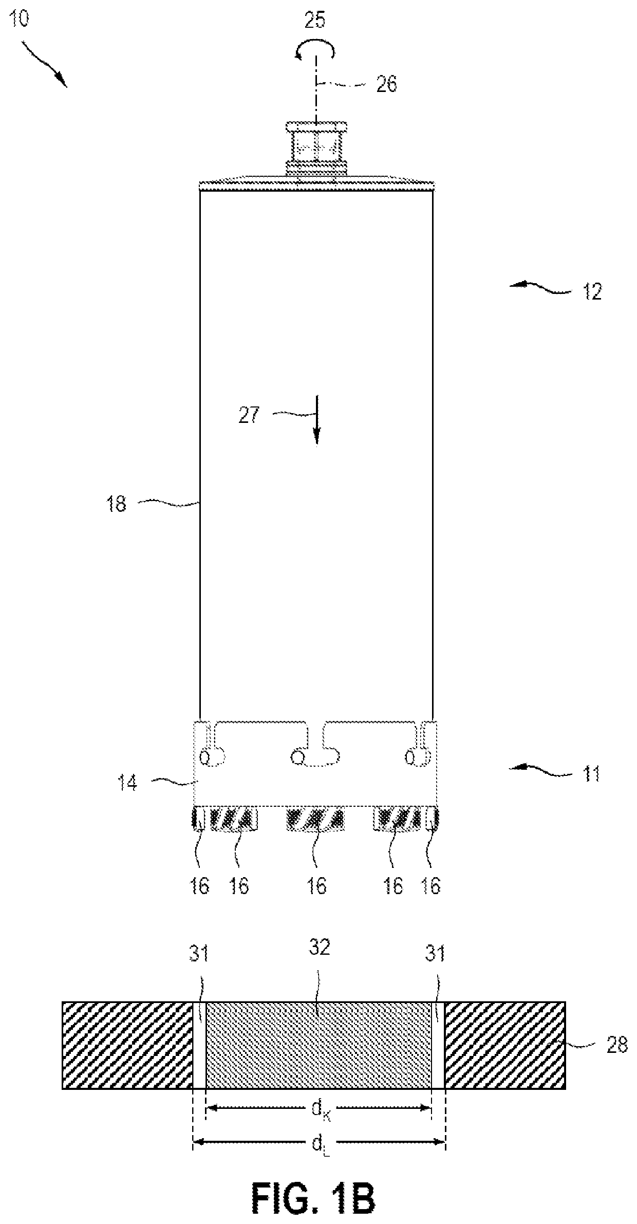
[0028]FIGS. 1A and 1B show a drill bit 10 which comprises a cutting section 11 and a drill shaft section 12, wherein the cutting section 11 and the drill shaft section 12 are connectable via a releasable connecting device 13. In this case, FIG. 1A shows the cutting section 11 and drill shaft section 12 in an unconnected state of the drill bit, and FIG. 1B shows the cutting section 11 and drill shaft section 12 in a connected state of the drill bit.

[0029]The cutting section 11 comprises a closed tubular element 14 and a plurality of drill segments 16 which are connected to the closed tubular element 14. The cutting section 11 is produced with the aid of the method according to the invention for producing a cutting section. The tubular element 14 is produced from two flat sheet metal parts which are connected to each other and are formed into an open tubular element. The open tubular element becomes a closed tubular element by connection of the abutting edges.

[0030]The drill segments ...


PUM

PropertyMeasurementUnit
thicknessaaaaaaaaaa
heightaaaaaaaaaa
tensileaaaaaaaaaa

Abstract

A method for producing a cutting section from a closed tubular element (14) which is in the form of a hollow cylinder and from one or more drill segments (16) which are connected to the closed tubular element (14).

Description

TECHNICAL FIELD[0001]The present invention relates to a method for producing a cutting segment for a drill bit.BACKGROUND[0002]WO 2014 / 096359 A1 discloses a cutting section for a drill bit, which cutting section is connectable to a drill shaft section of the drill bit via a releasable connecting device. The releasable connecting device is designed here as a combined push and twist connection. A “push and twist connection” refers to releasable connections between a first and a second connecting element, said connecting elements forming a push connection in one direction and being additionally connected via a twist connection. The cutting section comprises one or more drill segments, a ring section, an outer push element and an annular stop shoulder at the transition from the ring section to the outer push element.[0003]Cutting sections which are connectable with a combined push and twist connection are sold under the product name “Hilti DD X-CM”. The “Hilti DD X-CM” cutting sections ...

Claims


Application Information

Patent Timeline
Patent Type & Authority Patents(United States)
IPC IPC(8): B23P15/28B23B51/04
CPCB23P15/28B23B51/04B21D39/04B23D65/00B28D1/041
Inventor SCHROEDER, FLORIANDOMANI, GUENTERRONG, PINGYAN
Owner HILTI AG
Why Eureka
Try Eureka