Optical and electrical hybrid beamforming transmitter, receiver, and signal processing method

a beamforming transmitter and hybrid technology, applied in the field of communication technology, can solve the problems of difficult to achieve the above requirements, difficult to configure the microwave frequency band in the fifth-generation (5g) mobile communication, and scarce radio frequency band resources, and achieve the effect of reducing elements

Active Publication Date: 2022-11-01
TMY TECH INC
View PDF21 Cites 1 Cited by
  • Summary
  • Abstract
  • Description
  • Claims
  • Application Information

AI Technical Summary

Benefits of technology

[0011]Based on the above, in the optical and electrical hybrid beamforming transmitter, receiver, and signal processing method in the embodiments of the disclosure, the photoelectric converter is provided to each antenna of the transmitter, and the electric-to-optic converter is provided to each antenna of the receiver, to adjust the phase of the electric signals (that is, to delay the signals) and enable the phase of the signals of each channel to meet the requirement of the beam pattern of the antenna. Accordingly, different from a conventional architecture, a wavelength division multiplexer (WDM) and variable delay line (VDL) do not need to be set in an architecture of the disclosure, thereby reducing elements. In addition, different from conventional optical beamforming, an optical-electrical hybrid beamforming architecture of the embodiments of the disclosure may be easily adjusted to a specified phase, and a phase calibration is thus completed.

Problems solved by technology

On the other hand, radio frequency band resources are becoming scarce.
For example, it is difficult for a microwave frequency band configured in fifth-generation (5G) mobile communications to meet a high-bandwidth requirement.
The above requirements are relatively difficult to execute.

Method used


Image

  • Optical and electrical hybrid beamforming transmitter, receiver, and signal processing method
  • Optical and electrical hybrid beamforming transmitter, receiver, and signal processing method
  • Optical and electrical hybrid beamforming transmitter, receiver, and signal processing method

Examples


Embodiment Construction

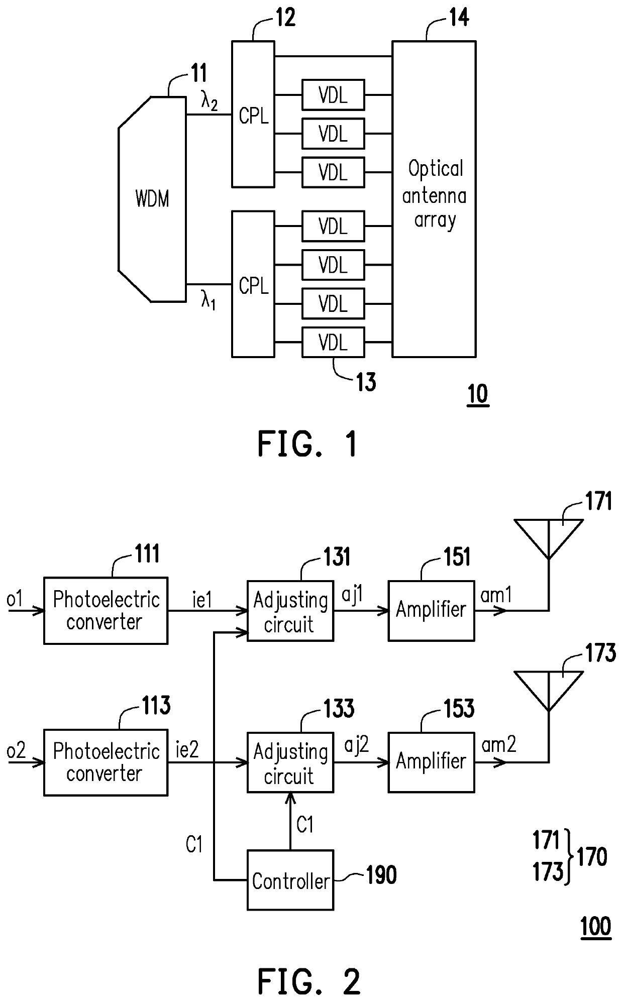
[0023]FIG. 2 is a block diagram of elements of an optical and electrical hybrid beamforming transmitter 100 according to an embodiment of the disclosure. Referring to FIG. 2, a transmitter 100 includes (but is not limited to) photoelectric converters 111 and 113, adjusting circuits 131 and 133, an antenna array 170, and a controller 190.

[0024]The photoelectric converters 111 and 113 may be photodiodes (PDs), optical detectors, or other optical sensors that convert light into current or voltage signals. In an embodiment, the photoelectric converters 111 and 113 convert optical signals o1 and o2 into initial electric signals ie1 and ie2, respectively.

[0025]The adjusting circuits 131 and 133 are coupled to the photoelectric converters 111 and 113, respectively. The adjusting circuits 131 and 133 may be chips, application specified integrated circuits (ASICs), field programmable gate arrays (FPGAs), microcontrollers, or other types of circuits.

[0026]In an embodiment, the adjusting circu...


PUM

PropertyMeasurementUnit
phaseaaaaaaaaaa
electricalaaaaaaaaaa
electricaaaaaaaaaa

Abstract

An optical and electrical hybrid beamforming transmitter, receiver, and signal processing method are provided. The transmitter includes, but is not limited to, two photoelectric converters, two adjusting circuits, and an antenna array. The photoelectric converter converts an optical signal into an initial electric signal, respectively. The adjusting circuit is coupled to the photoelectric converter, and are adapted for delaying the initial electric signal according to an expected beam pattern formed by the antenna array, respectively, to output an adjusted electric signal. The antenna array includes two antennas that are coupled to the adjusting circuit. The antenna radiates electromagnetic wave according to the adjusted electric signal. Accordingly, a phase of the signal may be adjusted, and the number of the elements may be reduced.

Description

CROSS-REFERENCE TO RELATED APPLICATION[0001]This application claims the priority benefit of Taiwan patent application no. 109142328, filed on Dec. 2, 2020. The entirety of the above-mentioned patent application is hereby incorporated by reference herein and made a part of this specification.BACKGROUNDTechnical Field[0002]The disclosure relates to a communication technology, and in particular to an optical and electrical hybrid beamforming transmitter, receiver, and signal processing method.Description of Related Art[0003]With a rapid development of wireless communication technology, a demand for related application services (such as high definition video or music streaming, movie downloading, virtual reality (VR), etc.) has increased. In order to meet a bandwidth requirement of the services, an antenna array with a high energy gain and directivity has been proposed to increase a signal noise ratio (SNR).[0004]On the other hand, radio frequency band resources are becoming scarce. For...

Claims


Application Information

Patent Timeline
Patent Type & Authority Patents(United States)
IPC IPC(8): H04B10/2575H04B1/00H04B1/04
CPCH04B10/25759H04B1/0096H04B1/04H04B2001/0491H04B2210/006
Inventor CHANG, SU-WEICHUANG, HAN-TITSAI, WEN-TSAIHUNG, TZU-CHIEHTAI, YANGHSU, SHAO-CHUNSU, GUO-ZHEN
Owner TMY TECH INC
Why Eureka
Try Eureka