Package substrate dividing method

a technology of packaging substrate and dividing method, which is applied in the direction of basic electric elements, semiconductor/solid-state device manufacturing, electrical equipment, etc., can solve the problems of dragging the side surface of each electrode, difficult to completely set the cutting blade at the same position, etc., to reduce the production of odd-form device packages, reduce the possibility of short circuit, and remove efficiently

Active Publication Date: 2022-11-01
DISCO CORP
View PDF7 Cites 0 Cited by
  • Summary
  • Abstract
  • Description
  • Claims
  • Application Information

AI Technical Summary

Benefits of technology

[0006]It is therefore an object of the present invention to provide a package substrate dividing method which can reduce the possibility of short circuit, defective mounting, and production of odd-form chips in dividing a package substrate into a plurality of device packages.
[0009]The dividing method according to the present invention includes the steps of forming a groove on the mount surface of the package substrate (half cutting the package substrate) along each division line so that the groove has a depth corresponding to the finished thickness, next removing the burrs produced in the groove forming step, and next grinding the sealing layer of the package substrate to thereby divide the package substrate into the plural device packages. Accordingly, the possibility of short circuit, defective mounting, and production of odd-form device packages can be reduced.
[0010]In the case that a liquid is sprayed toward the mount surface of the package substrate in the burr removing step, thereby removing the burrs, the burrs can be removed efficiently without adversely affecting the package substrate.

Problems solved by technology

In this full-cutting step, the side surface of a cutting blade comes into contact with the side surface of each electrode exposed in the half-cutting step, causing a drag of the side surface of each electrode.
Accordingly, it is difficult to set the cutting blade at completely the same position as that of the half-cut groove formed on the front side of the package substrate in fully cutting the package substrate from the back side.
In this case, there arises a problem even when the position of the groove formed on the back side of the package substrate is completely the same as the position of the half-cut groove formed on the front side of the package substrate.

Method used


Image

  • Package substrate dividing method
  • Package substrate dividing method
  • Package substrate dividing method

Examples


Embodiment Construction

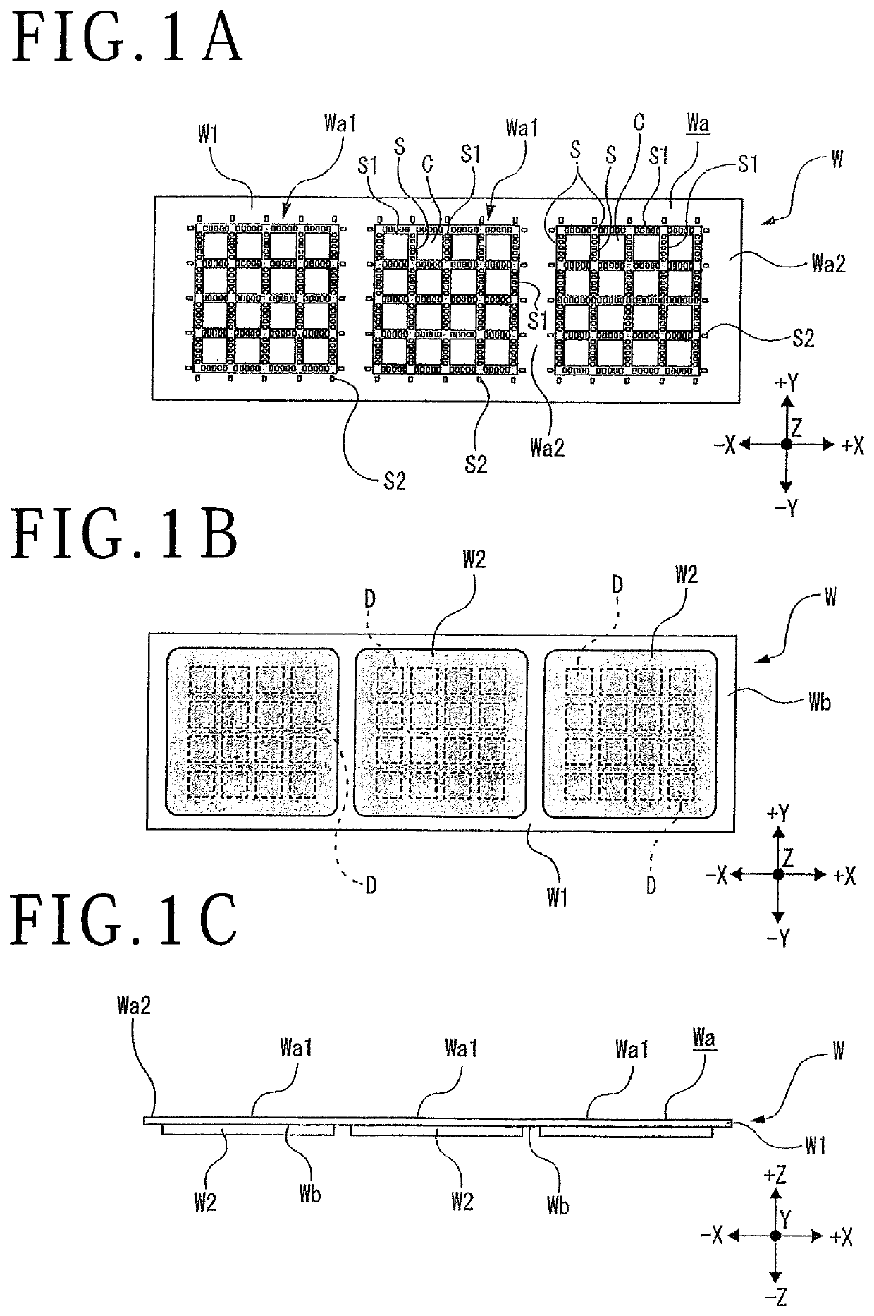
[0019]FIGS. 1A to 1C depict a package substrate W. For example, the package substrate W is a QFN substrate. The package substrate W has a base substrate W1 having a rectangular outside shape. The base substrate W1 is formed of metal such as 42 alloy (alloy of iron and nickel) and copper.

[0020]As depicted in FIG. 1A, the base substrate W1 has a front side as a mount surface Wa. A plurality of (e.g., three as depicted) device areas Wa1 are formed on the mount surface Wa. In each device area Wa1, a plurality of crossing division lines S are formed on the mount surface Wa to divide the device area Wa1 into individual device packages C respectively including devices D. That is, each device area Wa1 is divided along the division lines S by the method of the present invention. The crossing division lines S are composed of a plurality of parallel division lines S extending in a first direction and a plurality of parallel division lines S extending in a second direction perpendicular to the ...


PUM


Abstract

A method for dividing a package substrate into a plurality of device packages. The package substrate has a mount surface on the front side where a plurality of division lines are formed and a sealing layer formed on the back side, in which devices are sealed. The method includes a groove forming step of forming a groove along each division line on the mount surface of the package substrate so that the groove has a depth corresponding to a finished thickness of each device package, a burr removing step of removing burrs produced from electrodes in the groove forming step, and a grinding step of grinding the sealing layer of the package substrate so that a thickness of the package substrate is reduced to the finished thickness, after performing the burr removing step, thereby dividing the package substrate into the plural device packages.

Description

BACKGROUND OF THE INVENTIONField of the Invention[0001]The present invention relates to a method for dividing a package substrate into a plurality of device packages.Description of the Related Art[0002]In cutting a package substrate such as a quad flat non-leaded package (QFN) substrate and a chip size package (CSP) substrate or cutting a plate-shaped workpiece having metal (ductile material) on each division line, burrs are produced from the metal. The production of such burrs may cause a short circuit of wiring or there is a possibility that the burrs may fall in handling the package substrate in a subsequent step, causing defective mounting of the device chips on a printed wiring board or the like.[0003]To solve these problems, there has been proposed a method including the steps of half cutting the front side of the package substrate to form a half-cut groove on the front side of the package substrate and next spraying high-pressure water to the front side of the package substra...

Claims


Application Information

Patent Timeline
Patent Type & Authority Patents(United States)
IPC IPC(8): H01L21/78H01L21/304
CPCH01L21/78H01L21/3043H01L21/67092
Inventor CHOONG, WAI KITCHONG, ERIC
Owner DISCO CORP
Why Eureka
Try Eureka