
Resin dispenser for additive manufacturing

a technology of additive manufacturing and dispensers, applied in the field of additive manufacturing, can solve the problems of general slowness of techniques

Active Publication Date: 2022-10-04
CARBON INC
View PDF107 Cites 1 Cited by
  • Summary
  • Abstract
  • Description
  • Claims
  • Application Information

AI Technical Summary

Benefits of technology

The patent describes a method for making three-dimensional objects using a blended resin made from two different resins that produce objects with different mechanical properties. The resins are mixed together and dispensed to an additive manufacturing apparatus, where they solidify to produce the object. The resulting object has a unique combination of mechanical properties that are between those of the two resins. The method also includes steps of enriching the blended resin with oxygen or depleting it of nitrogen, and optionally curing the object. The use of a pseudoplastic composition with solid particles dispersed therein can further enhance the mechanical properties of the object.

Problems solved by technology

Unfortunately, such techniques have been generally considered slow, and have typically been limited to resins that produce brittle or fragile objects suitable only as prototypes.

Method used


Image

  • Resin dispenser for additive manufacturing
  • Resin dispenser for additive manufacturing
  • Resin dispenser for additive manufacturing

Examples


examples 1-6

[0114]As discussed below, it was found that, by simply blending two different dual cure resins—for example, one for a rigid polyurethane product, and one for an elastomeric polyurethane product, with both provided in the form of dual precursor resins—parts can be created with mechanical properties intermediate between the two, and with adequate toughness and durometer scores.

[0115]Results of Dynamic Mechanical Analysis (DMA) discussed below gives insight into the glass transition temperature (Tg), heat deflection temperature (HDT), and susceptibility to creep (Tan D) across a temperature range of −100° C. to 200° C., for three different blends, and shows that two different resin systems (RPU70 and EPU40, available from Carbon Inc., 1028 Mills Way, Redwood City, Calif. 94063 USA) can be used to conveniently generate a range of different product properties.

example 1

RPU70+EPU40 Storage Modulus

[0116]FIG. 6 shows the storage moduli for various blends of RPU70 and EPU40. As can be seen, the onset of glass transition for neat RPU70 is 72° C. Further, upon blending EPU40 with RPU70 in 30%, 40%, and 50% ratios (by mass), the glass transition temperature was progressively lowered to 43° C., 37° C., and 31° C. respectively.

example 2

RPU70+EPU40 Room Temperature Storage Modulus

[0117]Upon considering the room temperature storage modulus as shown in FIG. 7, a substantial change in stiffness was seen. From neat RPU70 to a RPU70-EPU40 70%-30% mixture, a drop by half is seen. Further, a drop by roughly 200 MPa for each 10% increase in EPU40 is seen.


PUM

PropertyMeasurementUnit
diameteraaaaaaaaaa
diameteraaaaaaaaaa
diameteraaaaaaaaaa

Abstract

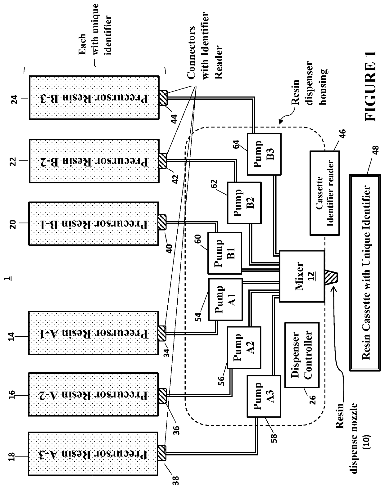
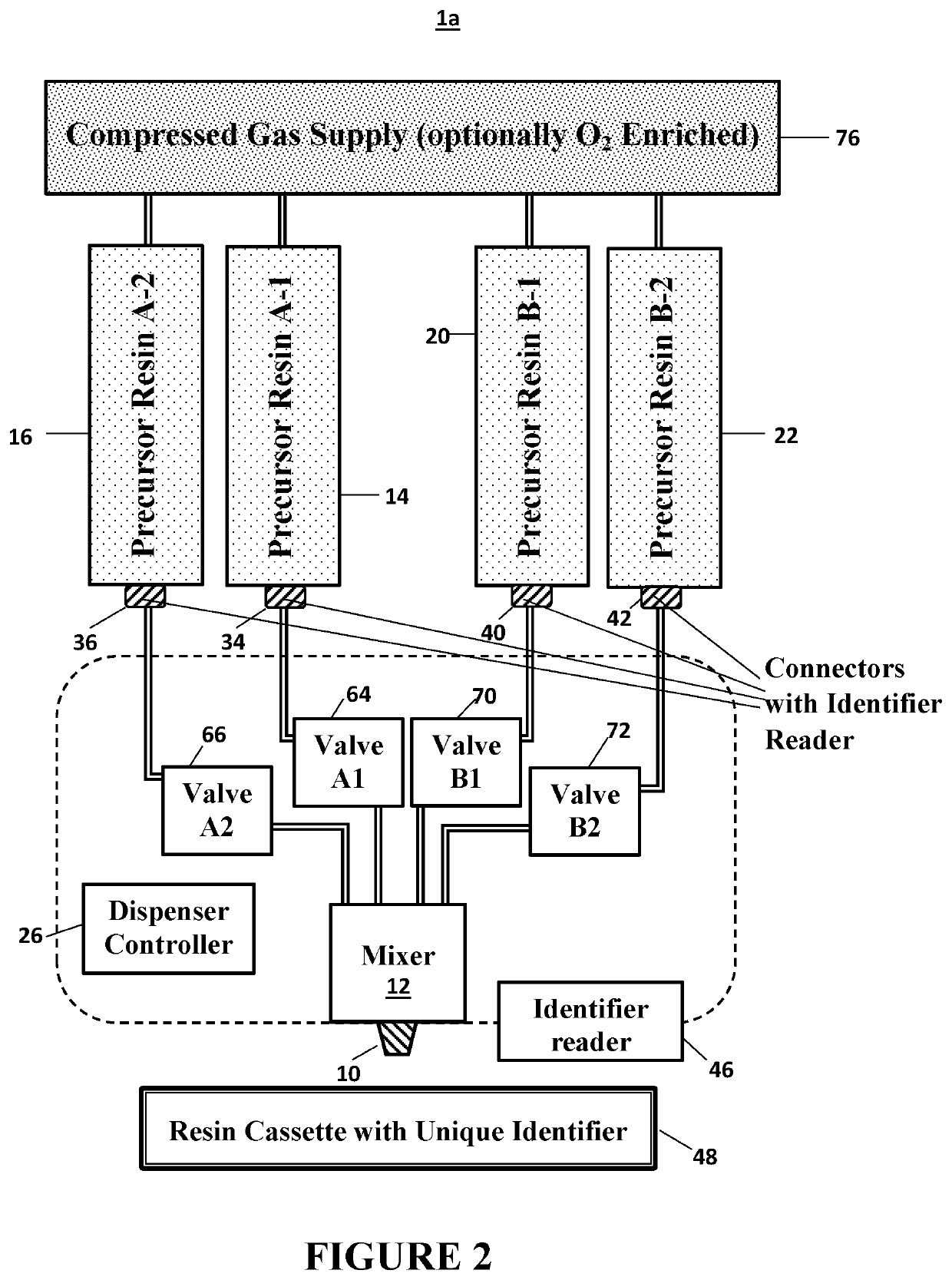
A method of making a three-dimensional object by additive manufacturing from a blended resin (e.g., a blended dual cure resin), the blended resin including (i) at least one light polymerizable first component and, (ii) optionally but preferably, at least one, or a plurality of, second solidifiable components that are different from said first component, the method including one or more of the steps of: (a) providing a first resin and a second resin, where the resins produce three-dimensional objects having different mechanical properties from one another when all are produced under the same process conditions; (b) mixing the first and second resins with one another to produce the blended resin, the blended resin producing a three-dimensional object having mechanical properties intermediate between that of objects produced by the first and second resins when all are produced under the same process conditions; and (c) dispensing the blended resin to the build region of an additive manufacturing apparatus; and then (d) optionally but preferably producing a three-dimensional object from the blended resin in the apparatus.

Description

RELATED APPLICATIONS[0001]This application is a 35 U.S.C. § 371 national phase entry of International Application No. PCT / US2018 / 038550, filed Jun. 20, 2018, which claims priority to U.S. Provisional Application Nos. 62 / 522,949, filed Jun. 21, 2017, and 62 / 525,364, filed Jun. 27, 2017, the disclosures of which are incorporated by reference herein in their entireties.FIELD OF THE INVENTION[0002]The present invention concerns additive manufacturing, and particularly concerns a resin dispensing apparatus for additive manufacturing.BACKGROUND OF THE INVENTION[0003]Some additive manufacturing techniques, particularly bottom-up and top-down stereolithography, make a three-dimensional object by light polymerization of a resin (see, e.g., U.S. Pat. No. 5,236,637 to Hull). Unfortunately, such techniques have been generally considered slow, and have typically been limited to resins that produce brittle or fragile objects suitable only as prototypes.[0004]A more recent technique known as conti...

Claims


Application Information

Patent Timeline
Patent Type & Authority Patents(United States)
IPC IPC(8): B29C64/124B29C64/314B29C64/321B29C64/364B29C64/245B29C64/255B29C64/393B29C64/35B29C64/205B33Y10/00B33Y30/00B33Y50/02B33Y40/20B29K63/00B29K75/00B29K83/00
CPCB29C64/124B29C64/205B29C64/245B29C64/255B29C64/314B29C64/321B29C64/35B29C64/364B29C64/393B29K2063/00B29K2075/02B29K2083/00B33Y10/00B33Y30/00B33Y40/20B33Y50/02G03F7/0037B33Y70/00B29C64/336G03F7/16G03F7/38B01F33/848B01F35/7176
Inventor ROLLAND, JASON P.CONVERSE, COURTNEY F.NAZARIAN, OSHINPANZER, MATTHEW
Owner CARBON INC
Learn More