True time delay circuit based on an optical waveguide switching array for RF phased array antenna beam steering

a technology of phased array and switching array, which is applied in the direction of instruments, non-linear optics, optics, etc., can solve the problems of limited operation bandwidth, side-lobe increase, and provide a very large cascaded time delay with a very small foot-print, and achieve high system scalability, high scalability, and superior technology

Active Publication Date: 2022-09-27
UNITED STATES OF AMERICA THE AS REPRESENTED BY THE SEC OF THE ARMY
View PDF5 Cites 0 Cited by
  • Summary
  • Abstract
  • Description
  • Claims
  • Application Information

AI Technical Summary

Benefits of technology

The patent describes a new technology for creating chippy, tunable optical delay lines for use in phased array antennas and electronic warfare systems. This technology offers high bandwidth, low cost, small size, and easy scalability. It uses a special switching matrix to manipulate RF signals in the optical domain, allowing for precise and wideband operation. The technology is based on a micro-ring switch and waveguide dispersion, and is mechanically stable without any moving parts. Overall, the technology offers a promising solution for improving the performance of phased array antennas and related applications.

Problems solved by technology

Limitations of existing approaches for providing the array of RF signals include bulky (table-top size) and heavy systems, limited operation bandwidth, performance problems due to intensity and phase fluctuations causing side-lobe increases, and expense.
The cascaded array architecture of some embodiments herein provides very large cascaded time delay with a very small foot-print.

Method used


Image

  • True time delay circuit based on an optical waveguide switching array for RF phased array antenna beam steering
  • True time delay circuit based on an optical waveguide switching array for RF phased array antenna beam steering
  • True time delay circuit based on an optical waveguide switching array for RF phased array antenna beam steering

Examples


Embodiment Construction

[0023]The embodiments herein and the various features and advantageous details thereof are explained more fully with reference to the non-limiting embodiments that are illustrated in the accompanying drawings and detailed in the following description. Descriptions of well-known components and processing techniques are omitted so as to not unnecessarily obscure the embodiments herein. The examples used herein are intended merely to facilitate an understanding of ways in which the embodiments herein may be practiced and to further enable those of skill in the art to practice the embodiments herein. Accordingly, the examples should not be construed as limiting the scope of the embodiments herein.

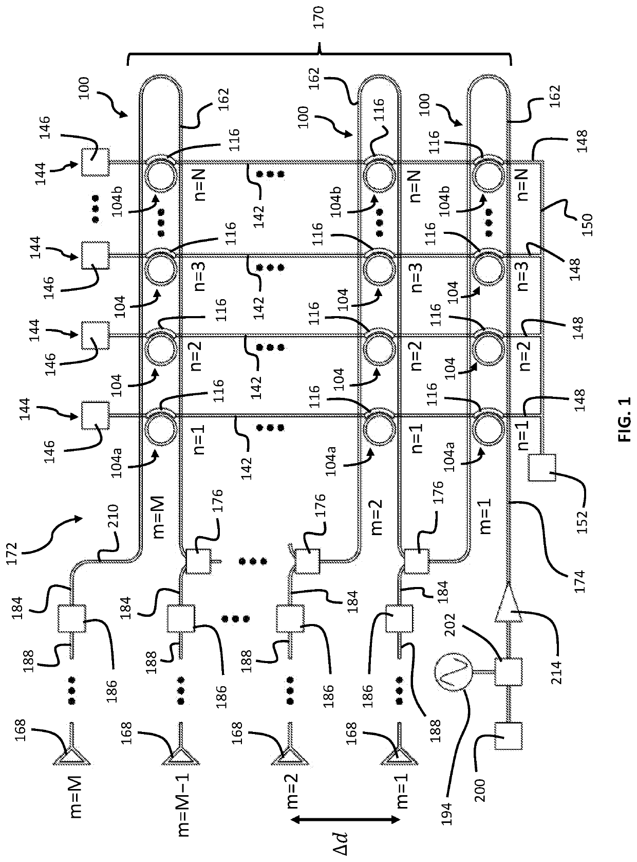
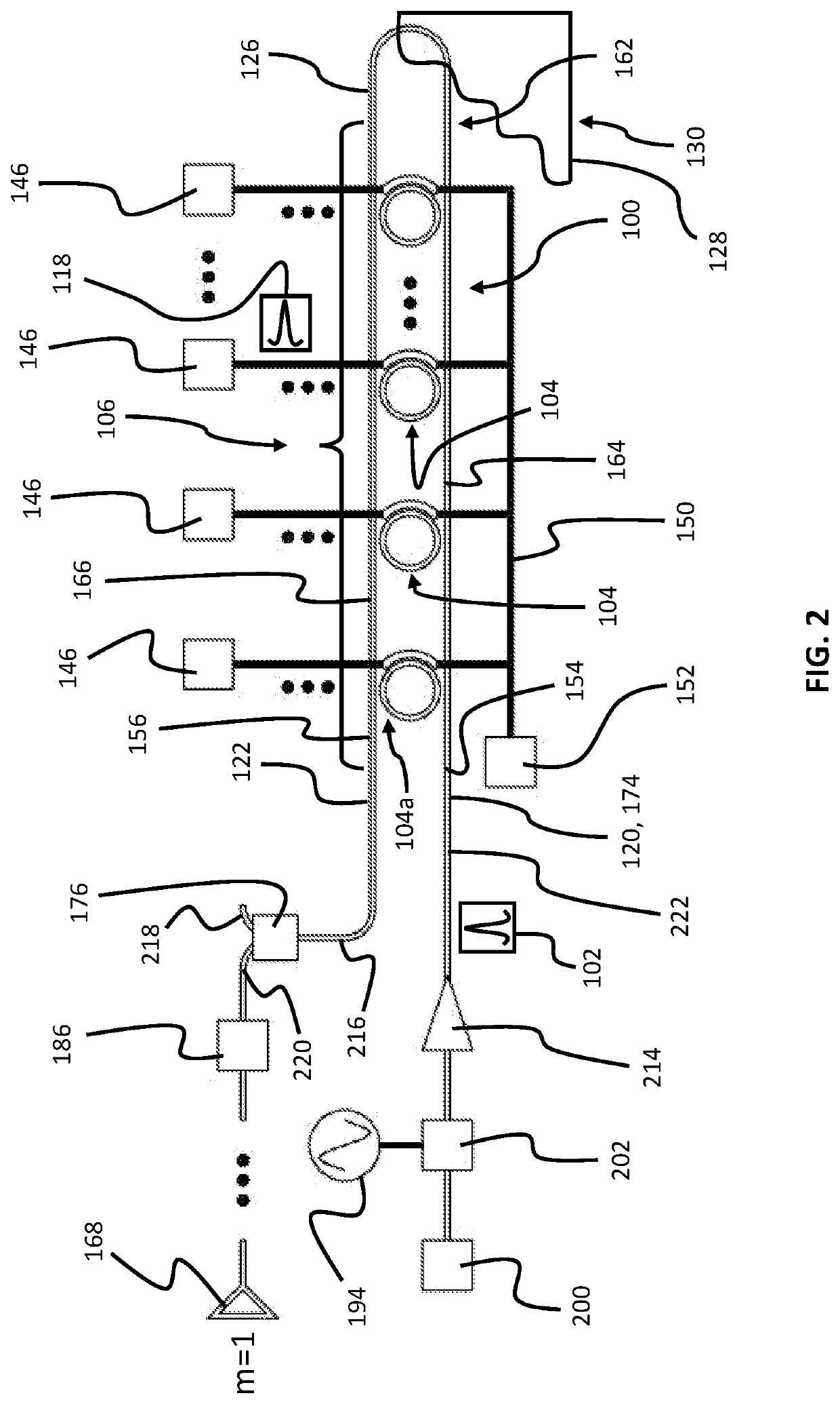
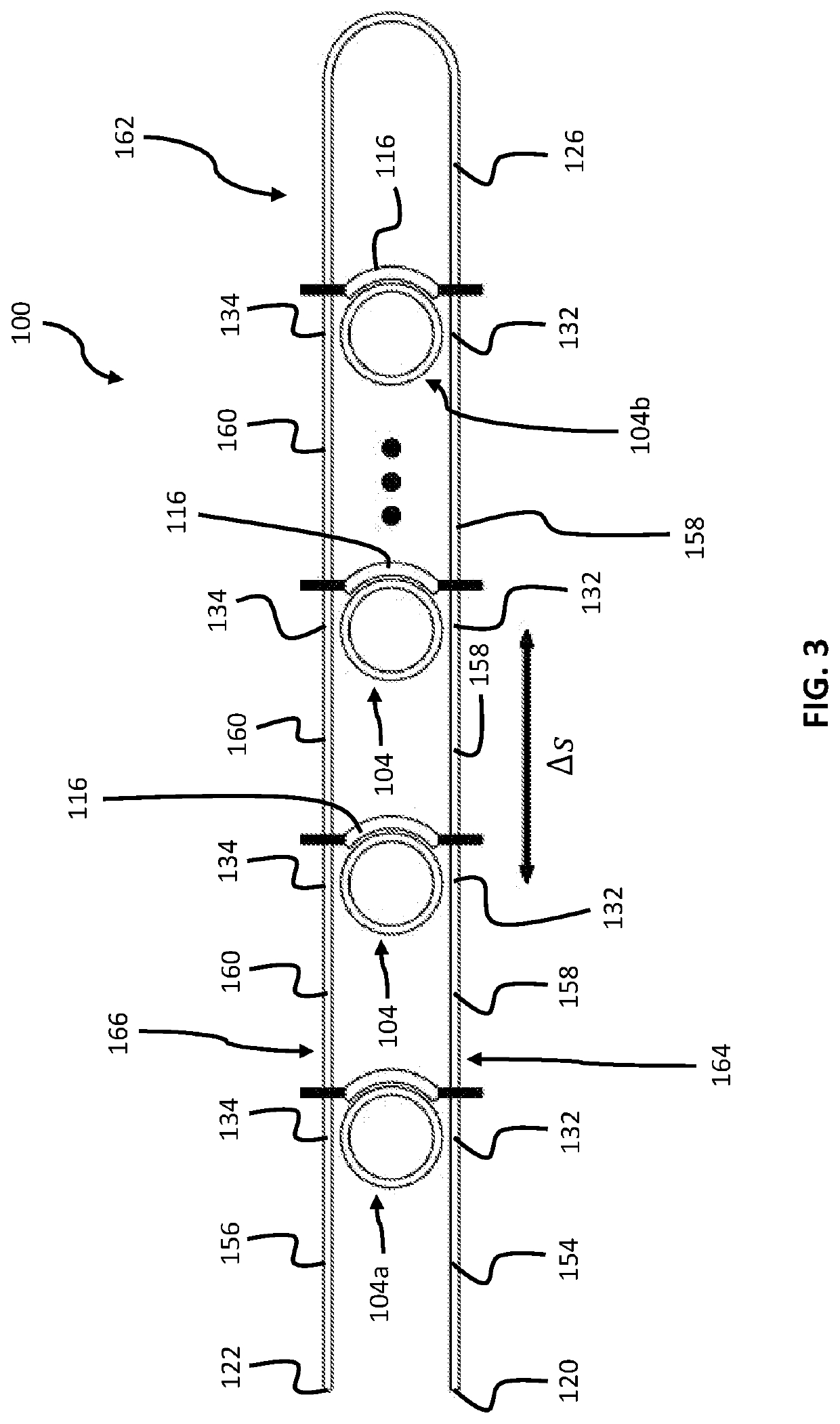
[0024]Referring to FIGS. 1 through 13, some embodiments herein are directed to a time delay device 100 for producing a time delay of a time delay increment in an optical signal 102. The time delay device includes a plurality of four-port switches 104, 104a, and 104b. The plurality of four-port ...


PUM

PropertyMeasurementUnit
time delayaaaaaaaaaa
optical path lengthaaaaaaaaaa
refractive indexaaaaaaaaaa

Abstract

Time delay devices for producing tunable time delays in optical signals. Cascades of the time delay devices can be used for beam steering in phased-array antennas. The time delay may be produced by selecting a time delay between an input and output of the time delay device from any of the time delay obtained by all four-port switches of the time delay device being in an OFF state and time delays obtainable by switching any one of the four-port switches to an ON state; and producing the selected time delay between the input and output of the time delay device by performing any of avoiding an application of an electrical control signal to any of electro-optic switch elements of the time delay device and applying the electrical control signal to one of the electro-optic switch elements that corresponds to a four-port coupler corresponding to the selected time delay.

Description

GOVERNMENT INTEREST[0001]The embodiments herein may be manufactured, used, and / or licensed by or for the United States Government without the payment of royalties thereon.BACKGROUNDTechnical Field[0002]The embodiments herein generally relate to apparatuses and methods for providing tunable delays in optical and RF signals and their applications.Description of the Related Art[0003]Steering of transmitted radio frequency (RF) beams using phased antenna arrays is increasingly vital to radar and telecommunication technologies. Arrays of time (i.e., phase) delayed RF inputs with a tunable time delay are used for this type of RF beam steering. Limitations of existing approaches for providing the array of RF signals include bulky (table-top size) and heavy systems, limited operation bandwidth, performance problems due to intensity and phase fluctuations causing side-lobe increases, and expense. There remains a need for improved systems for producing tunable phased arrays of RF signals that...

Claims


Application Information

Patent Timeline
Patent Type & Authority Patents(United States)
IPC IPC(8): G02F1/295
CPCG02F1/2955G02F2203/15
Inventor CHO, SANG-YEONZHOU, WEIMIN
Owner UNITED STATES OF AMERICA THE AS REPRESENTED BY THE SEC OF THE ARMY
Why Eureka
Try Eureka