
Method and system for positioning a drilling or other large structure using attached positioning shoes with individually addressable wireless vertical and rotational control

a technology of positioning shoes and wireless vertical and rotation control, which is applied in the direction of drilling accessories, drilling machines and methods, earthwork drilling and mining, etc., can solve the problems of not being able to provide individually addressable shoes, not being able to permit individual manipulation of shoes, and known methods using structural shoes without the capability of presently disclosed subject matter, so as to enhance rig movement and minimize equipment. the effect of equipmen

Active Publication Date: 2022-09-27
CONTROLLED FLUIDS INC
View PDF5 Cites 0 Cited by
  • Summary
  • Abstract
  • Description
  • Claims
  • Application Information

AI Technical Summary

Benefits of technology

The present disclosure provides an enhanced rig moves system with automated Rig Walking that improves rig safety by removing workers from the drill site and minimizing the amount of equipment that needs to be disassembled for movement. The system also features divided work and multiplied efficiency, enhanced efficiency with precise positioning, and faster rig moves through synchronized expansion. Additionally, the system includes a modular and interchangeable positioning shoe that eliminates the need for a centralized or dedicated HPU, as well as all for "ground-hopping" of a single positioning shoe while detached from the rig for testing, servicing, and quality control.

Problems solved by technology

In the past, known methods used structural shoes but without the capability of the presently disclosed subject matter.
Known systems do not provide individually addressable shoes for the positioning or operation of the positioning shoe and, therefore, do not permit individual manipulation of the shoes for various positioning demands that may face a drilling rig operator.
Because known systems lack independent control of the positioning shoe, the maintenance and repair of a malfunctioning positioning shoe has proven both complicated and expensive.
Also, known rig positioning shoes fail to provide an effective slewing mechanism that permits variable rotational control and variation.

Method used


Image

  • Method and system for positioning a drilling or other large structure using attached positioning shoes with individually addressable wireless vertical and rotational control
  • Method and system for positioning a drilling or other large structure using attached positioning shoes with individually addressable wireless vertical and rotational control
  • Method and system for positioning a drilling or other large structure using attached positioning shoes with individually addressable wireless vertical and rotational control

Examples


Embodiment Construction

[0037]One or more embodiments of the invention are described below. It should be noted that these and any other embodiments are exemplary and are intended to be illustrative of the invention rather than limiting. While the invention is widely applicable to different types of systems, it is impossible to include all the possible embodiments and contexts of the invention in this disclosure. Upon reading this disclosure, many alternative embodiments of the present invention will be apparent to persons of ordinary skill in the art.

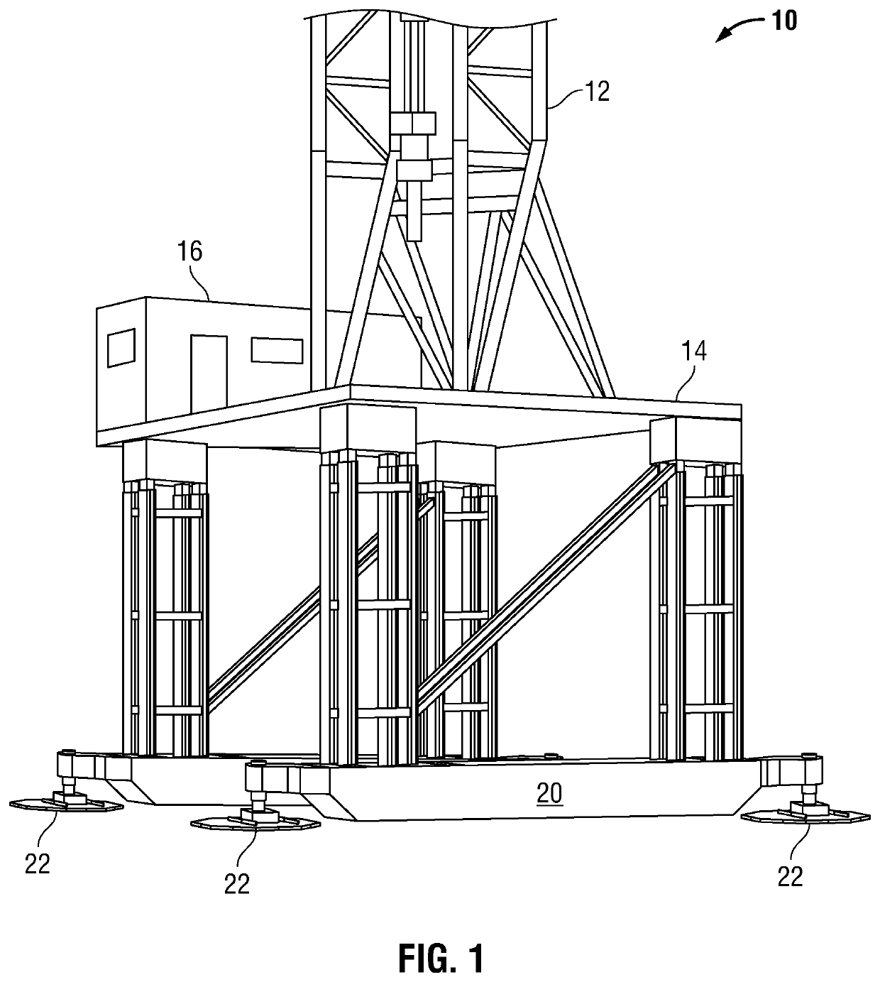
[0038]FIG. 1 illustrates drilling rig 10 which may be used for energy production in an oil field or similar venue. Drilling rig 10 includes superstructure 12 and platform 14. On platform 14 appears operator shack 16. In operator shack 16 reside controls, information, maps and office space for performing the operations necessary to operate and reposition drilling rig 10. Beneath platform 14 appear structural members 18 which provide physical support for drillin...


PUM


Abstract

A drilling rig mobility system moves a drilling rig or similar structure in an oilfield or similar environment and includes independently controllable positioning shoes attaching to the drilling rig and controllable through separate and coordinated position control commands. Each positioning shoe may be individually addressed to reposition the drilling rig. Each positioning shoe includes a hydraulic actuator and wireless control circuitry. The hydraulic actuator provides vertical and horizontal force in response to wireless control signals for wireless position and control data and instructions with a remote wireless communications device. A cylinder stomper vertically elevates the hydraulic actuator and receives and transfers the vertical force. A foot assembly transfers the horizontal force from the hydraulic actuator. A positioning shoe cylinder stomper and positioning shoe traverse cylinder provide infinitely variable position control. Rotational positioning may be manually or automatically achieved.

Description

CROSS REFERENCE TO RELATED APPLICATION[0001]This application claims benefit of U.S. patent application Ser. No. 16 / 154,311, now U.S. Pat. No. 10,472,892, entitled “METHOD AND SYSTEM FOR POSITIONING A DRILLING OR OTHER LARGE STRUCTURE USING ATTACHED POSITIONING SHOES WITH INDIVIDUALLY ADDRESSABLE WIRELESS VERTICAL AND ROTATIONAL CONTROL” filed on Oct. 78, 2018,FIELD OF THE INVENTION[0002]The present disclosure relates generally robotic and automated methods and systems for positioning a drilling or other large structure. The disclosed method and system use attached positioning shoes, each providing individually addressable vertical and rotational control through wireless communication and feedback for infinitely variable vertical position adjustment and rotational position control.BACKGROUND[0003]The subject matter of the present disclosure addresses moving a drill rig in the field without the assembly and disassembly of structural components. The result is to provide drilling rig po...

Claims


Application Information

Patent Timeline
Patent Type & Authority Patents(United States)
IPC IPC(8): E21B7/02E21B44/00E04B1/35E04H12/34E04B1/343
CPCE21B7/022E21B44/00E04B1/34331E04B2001/3588E04H12/345E21B7/024E21B15/003
Inventor CONN, III, EDWIN DIXONJACKSON, JUSTIN MICHAELALLEN, JASON PAULMARTENS, JAKE DEAN
Owner CONTROLLED FLUIDS INC
Learn More