
Main body frame for electric motorcycle and electric motorcycle

a technology for electric motorcycles and frame frames, which is applied in the direction of propulsion by batteries/cells, cycle equipment, steering devices, etc., can solve the problems of heavy frame made of steel tubes, not fully considering the potential of electric motorcycles, and adding significantly to the weight of electric motorcycles, etc., to achieve light weight, narrow width, and handle the effect of electric motorcycles

Active Publication Date: 2022-09-27
E-MOOVBE GMBH
View PDF24 Cites 7 Cited by
  • Summary
  • Abstract
  • Description
  • Claims
  • Application Information

AI Technical Summary

Benefits of technology

The present invention introduces enhancements to the existing technology of electric motorcycles. The main body frame is designed to be lightweight, narrow in width, and easy to handle. Furthermore, it can be produced without welding, making it possible to customize the motorcycle design. This results in an improved electric motorcycle design with improved performance and user experience.

Problems solved by technology

Such concept does not take full account of all potential of an electric motorcycle.
Therefore, a frame made from steel tubes is heavy and adds significantly to the weight of the electric motorcycle.
Such a conventional electric motorcycle is therefore relatively heavy, typically above 100 kg, for instance, 130 kg, and thus difficult to handle, in particular for beginners but also for professionals, for instance, when used for jumps in trial races.
Moreover, it is difficult to transport because it cannot be lifted by a single person and a common bicycle rack for transportation by car is not designed for such weight.
Moreover, as mentioned, steel tubes are usually welded together which does not allow to exchange parts.
This is hardly feasible with tubes which are welded together.
This makes it difficult to removably secure the tubes to each other in a stable manner since the material is too thin to provide a threaded portion of an appropriate length for engaging a screw.
The material is also too thin to receive the head of a countersunk head screw.
In addition, the local application of heat during welding can weaken the overall strength of the otherwise suitable materials such that materials for welded frames are undesirably limited, for instance, to specific steels.
Furthermore, welding damages a protective anodization.
A frame with only a central tubular column is, however, not suitable for an electric motorcycle with much heavier and larger battery and motor unit.
In particular, the diameter of cavities of the tubes also adds to the width of the frame, which typically results in a frame width of more than 30 cm.

Method used


Image

  • Main body frame for electric motorcycle and electric motorcycle
  • Main body frame for electric motorcycle and electric motorcycle
  • Main body frame for electric motorcycle and electric motorcycle

Examples


first embodiment

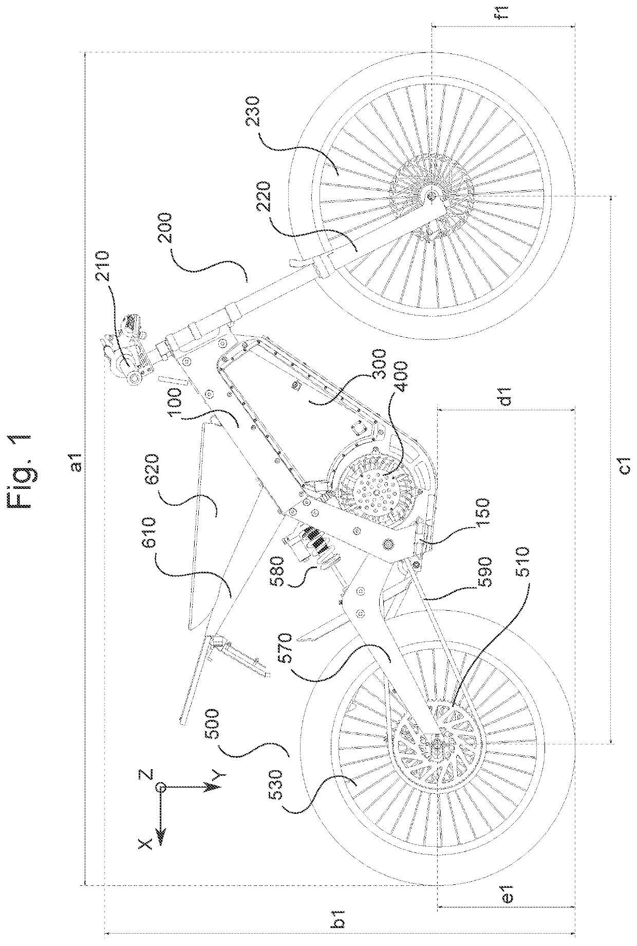
[0031]FIG. 1 is a side view illustrating an electric motorcycle according to the first embodiment of the present invention which incorporates a main body frame 100 to be described in details below. Pedals 150 for supporting the feet of a driver are attached to either side of the main body frame 100. A pivot stem of a front fork 200 is pivotally loaded to a front fork through hole of the main body frame 100. A battery unit 300 and a motor unit 400 are mounted to the lower side of the main body frame 100. A rear fork 500 is pivotally mounted to the main body frame 100. A seat support 610 is attached to the main body frame and a seat 620 for a driver is supported by the seat support 610 and the main body frame.

[0032]The front fork 200 comprises a steering bar 210 on its upper side for steering the motorcycle and front shock absorber(s) 220 on its lower side on which a front wheel 230 is pivotally mounted. The front fork is, for instance, of a dual crown fork type or of a single crown f...

second embodiment

[0086]In the first embodiment, as illustrated in FIG. 1, an electric motor cycle is described in which the motor unit 400 is removably secured to the main body frame 100 and placed in a rearward direction X and / or downward direction Y with respect to the battery unit 300. In order to secure more space for the battery unit 300, a motor unit can instead be arranged at the hub of the rear wheel 530 and / or at the hub of the front wheel 230. However, such an arrangement can unfavorably shift the center of gravity of the electric motorcycle, especially with regard to jumping.

[0087]The second embodiment differs from the first embodiment mainly by an arrangement of the motor unit 400 due to which more space can be provided for the battery unit 300 and an unfavorable shift of the center of gravity of the electric motorcycle can be avoided. The following description of the second embodiment focuses on the differences to the first embodiment. In particular, the description of the features or p...


PUM


Abstract

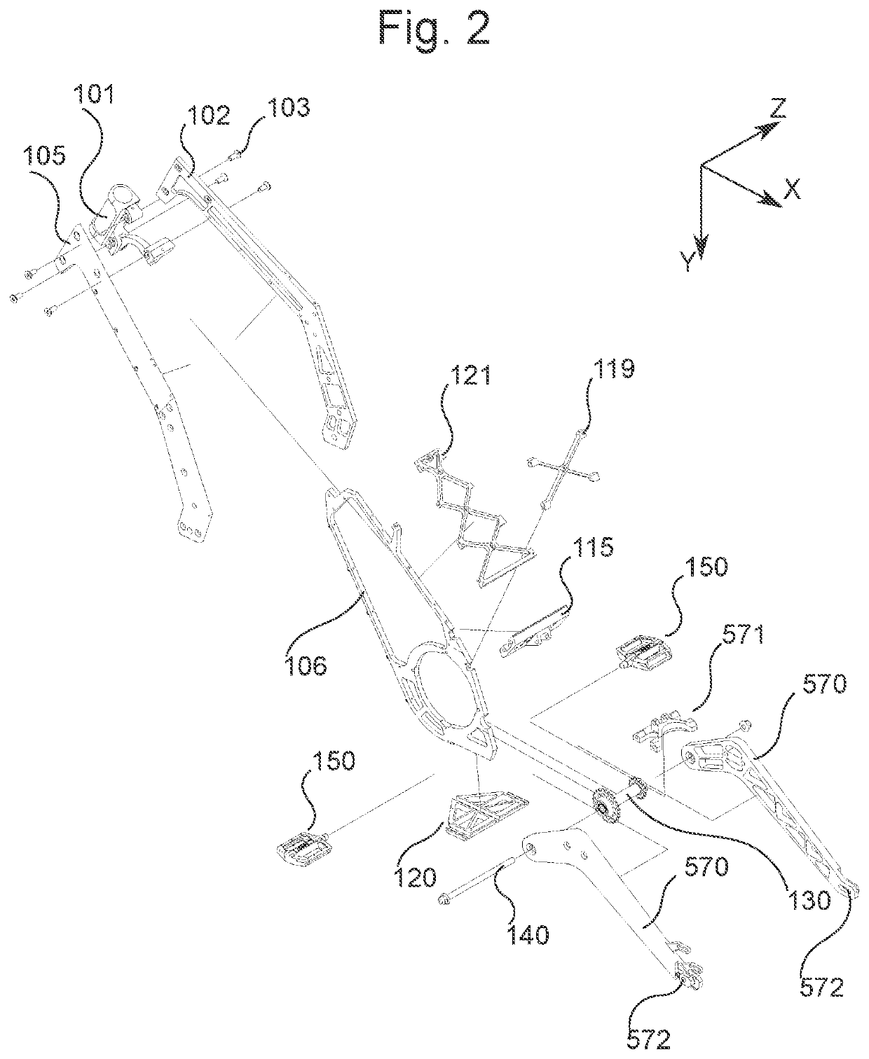
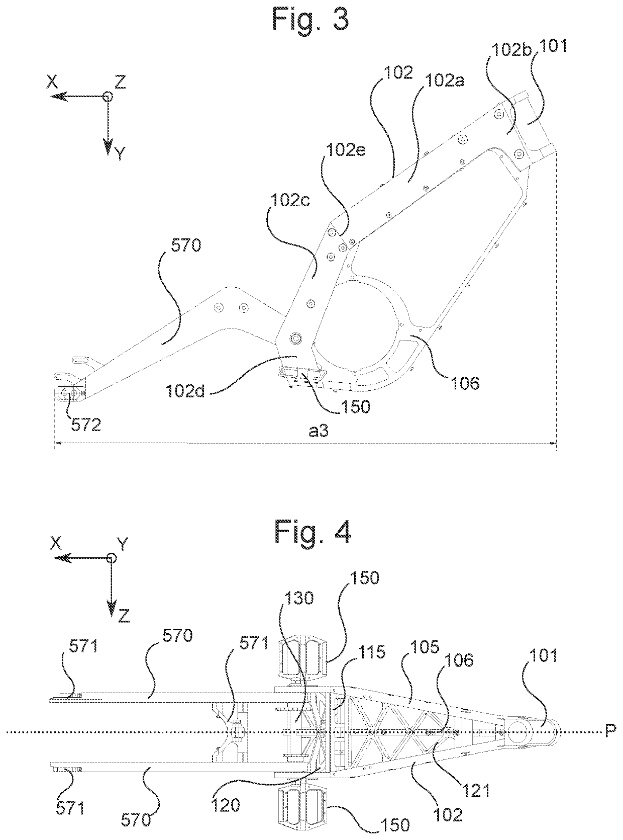
A main body frame (100) for an electric motorcycle comprises a front fork support member (101) with a front fork through hole for loading a pivot stem of a front fork (200), the front fork through hole has a pivotal axis arranged in a central plane (P) of the main body frame; the main body frame further comprises a right and a left frame part (102, 105) arranged on opposite sides of the central plane of the main body frame, each having an elongated shape and being formed of an upper part (102a, 102b) and a lower part (102c, 102d), respectively at different sides of an elongation direction changing portion (102e), a first buffer member (120) attached, at opposite sides thereof, to the right and the left frame part, and crossing the central plane. wherein starting from the respective elongation direction changing portions thereof. the upper parts of the left and the right frame part extend inwardly towards the central plane so as to embrace the front fork support member, and are attached to opposite sides of the front fork support member, and a largest width (a7) of the main body frame in a width direction (Z) perpendicular to the central plane is 10 cm or more and 30 cm or less.

Description

BACKGROUND OF THE INVENTIONField of the Invention[0001]The present invention relates to a main body frame for an electric motorcycle and an electric motorcycle comprising the main body frame.Description of the Related Art[0002]In the art, electric motorcycles are often developed based on the overall design of combustion engine motorcycles, wherein the frames are retained with only minor adaptations. Respective motorcycle frames are known, which are made from metal tubes which are suitably bent and welded together. Such concept does not take full account of all potential of an electric motorcycle.[0003]Also for an electric motorcycle, the frame has to be sufficiently rigid for coping with extreme situations and needs to have enough strength to sustain impacts to a certain amount, for example caused by falls. To fulfill these requirements, the tubes are usually made from steel such as ChroMoly steel. Steel has a relatively high density of about 7.75 to 8.05 g / cm3. Therefore, a frame m...

Claims


Application Information

Patent Timeline
Patent Type & Authority Patents(United States)
IPC IPC(8): B62K11/04B62J43/20B62J43/16B62J1/08B62K19/24B62K21/02B62M7/12B62J43/30
CPCB62K11/04B62J1/08B62J43/16B62J43/20B62K19/24B62K21/02B62M7/12B62J43/30B62K19/08B62K19/12B62K19/16B62K19/40B62K2204/00B62M7/02B60L50/66B60K1/04Y02T10/70B60L2200/10B60Y2200/12B60K7/0007B60K2007/0061B60K2007/0046
Inventor KUGELE, CHRISTIAN
Owner E-MOOVBE GMBH
Learn More