
Measurement system and method for positioning accuracy of a robotic arm

a robotic arm and positioning accuracy technology, applied in the direction of electrical/magnetic measuring arrangements, program-controlled manipulators, instruments, etc., can solve the problems of time-consuming operation, excessive hardware cost, and reduced yield, so as to accurately and quickly measure the positioning accuracy of the robotic arm

Active Publication Date: 2022-09-06
INSTITUTE FOR INFORMATION INDUSTRY
View PDF37 Cites 0 Cited by
  • Summary
  • Abstract
  • Description
  • Claims
  • Application Information

AI Technical Summary

Benefits of technology

The present invention provides a measurement system and method for positioning accuracy of a robotic arm. This system and method accurately and quickly measure the positioning accuracy of the robotic arm in three dimensions without generating pollution during the operation. The measurement is done by configuring magnetic elements between the robotic arm and a fixed platform, which generates a magnetic field to provide compensation information. This technology can be used without causing pollution such as oil stains during the robotic arm operation.

Problems solved by technology

However, the terminal of the robotic arm must have a certain degree of accuracy to avoid damage to the product or reduction of the yield of the product due to excessive error during the processing.
The laser interferometer can only measure the positioning accuracy of one axis in the three-degree space at a time, and has the problem of time-consuming operation.
The laser tracker has a fast and accurate measurement of high portability and positioning accuracy, but has a problem of excessive hardware cost.
The single camera can only capture information of two axes in a three-dimensional space, and the software and hardware required for the three-dimensional camera are very expensive.
Laser cross positioning technology has high accuracy, but it has the problem of measuring time too long and the cost of software and hardware too high.
Among the above positioning correction technologies, only the image sensor can detect the positioning accuracy during the use of the robotic arm, but the image sensor generates oil stain of the lubricating oil during use.

Method used


Image

  • Measurement system and method for positioning accuracy of a robotic arm
  • Measurement system and method for positioning accuracy of a robotic arm
  • Measurement system and method for positioning accuracy of a robotic arm

Examples


Embodiment Construction

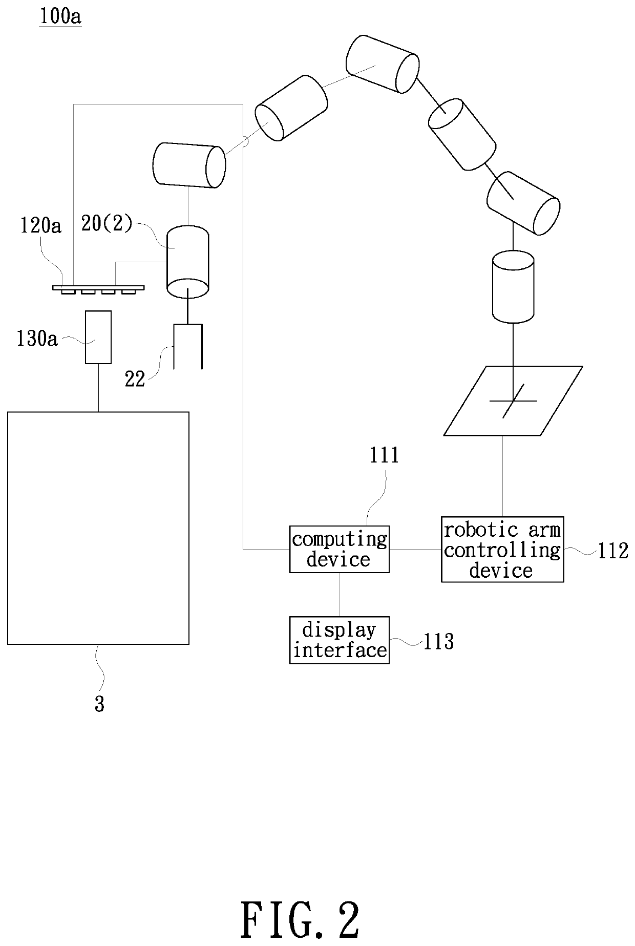
[0021]FIG. 1A is a schematic diagram of a measurement system for positioning accuracy of a robotic arm provided by an embodiment of the present invention. FIG. 1B is a schematic diagram of a transformation matrix for obtaining a coordinate system between a robotic arm and a fixed platform provided by an embodiment of the present invention. Please refer to FIG. 1A and FIG. 1B, a measurement system 100 for positioning accuracy of a robotic arm in the embodiment includes a robotic arm 2, a computing device 111, a robotic arm controlling device 112, a first magnetic element 120, and a second magnetic element 130 to measure the positioning accuracy of an operation end 21 of the robotic arm 2.

[0022]The robotic arm controlling device 112 is electrically connected to the robotic arm 2 and the computing device 111. The first magnetic element 120 is disposed on the robotic arm 2. The second magnetic element 130 is disposed on a fixed platform 3. One of the first magnetic element 120 and the s...


PUM


Abstract

A measurement system for positioning accuracy of a robotic arm includes the robotic arm, a computing device, a robotic arm controlling device, a first magnetic element and a second magnetic element. The robotic arm controlling device is electrically connected to the robotic arm and the computing device. The first magnetic element is disposed on a robotic arm. The second magnetic element is disposed on a fixed platform. One of the first magnetic element and the second magnetic element is electrically connected to the computing device. The robotic arm controlling device controls the robotic arm to move the first magnetic element above the second magnetic element to generate a magnetic field. The computing device is configured to calculate a plurality of movement error information of the first magnetic element in the magnetic field, and count the plurality of movement error information to obtain a positioning accuracy of the robot arm.

Description

FIELD OF THE INVENTION[0001]The present invention relates to a measurement technology of positioning accuracy, and more particularly to a measurement system and method for positioning accuracy of a robotic arm.BACKGROUND OF THE INVENTION[0002]Robotic arms have been used in many fields, such as part assembly or semiconductor wafer clamping. However, the terminal of the robotic arm must have a certain degree of accuracy to avoid damage to the product or reduction of the yield of the product due to excessive error during the processing.[0003]There are several positioning correction techniques for robotic arm terminals, such as laser interferometers, laser trackers, image sensors, and laser cross positioning technology. The laser interferometer can only measure the positioning accuracy of one axis in the three-degree space at a time, and has the problem of time-consuming operation. The laser tracker has a fast and accurate measurement of high portability and positioning accuracy, but ha...

Claims


Application Information

Patent Timeline
IPC IPC(8): B25J13/08B25J9/16G01D5/14G01B7/004
CPCB25J13/087B25J9/1694B25J13/088G01B7/004G01D5/145B25J19/0095B25J13/089
Inventor HUANG, YUNG-I
Owner INSTITUTE FOR INFORMATION INDUSTRY
Learn More