
Refrigeration system mixed-flow compressor

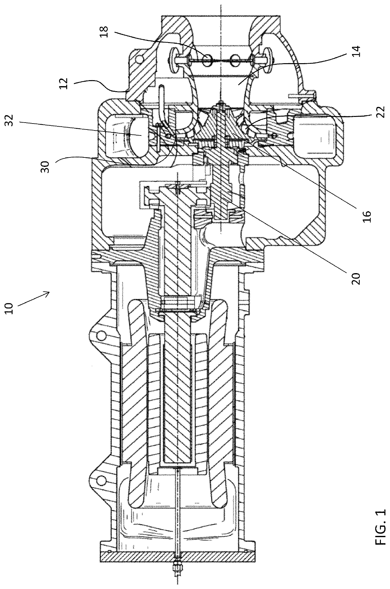
a compressor and refrigeration system technology, applied in the direction of machines/engines, liquid fuel engines, lighting and heating apparatus, etc., can solve the problem that the size of the package may exceed the available space within the packaging envelop

Active Publication Date: 2022-08-23
CARRIER CORP
View PDF34 Cites 3 Cited by
  • Summary
  • Abstract
  • Description
  • Claims
  • Application Information

AI Technical Summary

Benefits of technology

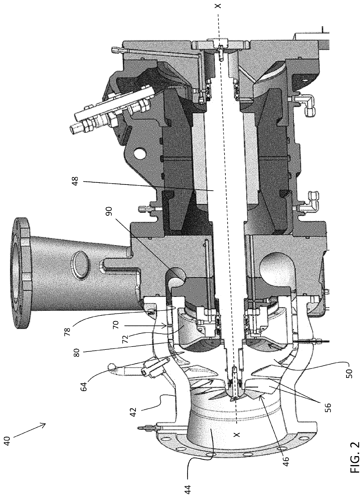
The design achieves a significant reduction in compressor size, up to 40% in radius and over 10% in length, while maintaining high pressure ratio performance, making it suitable for low and medium pressure refrigerants and eliminating the need for subsequent stages.

Problems solved by technology

However, these large sizes may exceed the available space within a packaging envelope.

Method used


Image

  • Refrigeration system mixed-flow compressor
  • Refrigeration system mixed-flow compressor
  • Refrigeration system mixed-flow compressor

Examples


Embodiment Construction

[0032]A detailed description of one or more embodiments of the disclosed apparatus and method are presented herein by way of exemplification and not limitation with reference to the Figures.

[0033]The term “about” is intended to include the degree of error associated with measurement of the particular quantity based upon the equipment available at the time of filing the application.

[0034]The terminology used herein is for the purpose of describing particular embodiments only and is not intended to be limiting of the present disclosure. As used herein, the singular forms “a”, “an” and “the” are intended to include the plural forms as well, unless the context clearly indicates otherwise. It will be further understood that the terms “comprises” and / or “comprising,” when used in this specification, specify the presence of stated features, integers, steps, operations, elements, and / or components, but do not preclude the presence or addition of one or more other features, integers, steps, ...


PUM


Abstract

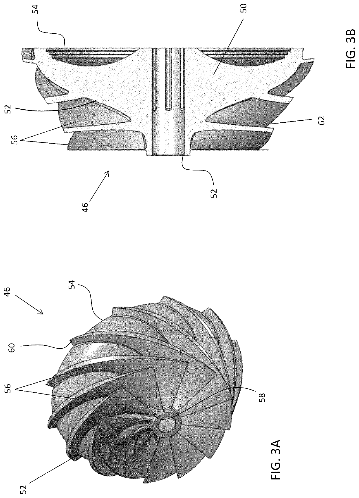
An impeller mountable within a centrifugal compressor includes a hub having a front side and a back side, the hub being rotatable about an axis of rotation and a plurality of vanes extending outwardly from the front side of the hub such that a plurality of passages is defined between adjacent vanes. The plurality of vanes is oriented such that a flow output from the plurality of passages adjacent the back side of the impeller is arranged at an angle to the axis of rotation of less than 20 degrees.

Description

CROSS-REFERENCE TO RELATED APPLICATIONS[0001]This application claims the benefit of U.S. Provisional Application Ser. No. 62 / 644,017, filed Mar. 16, 2018, which is incorporated herein by reference in its entirety.BACKGROUND[0002]Embodiments of the disclosure relate generally to a refrigeration system, and more particularly, to a compressor.[0003]Rotary machines are commonly used in refrigeration and turbine applications. An example of a rotary machine includes a centrifugal compressor having an impeller fixed to a rotating shaft. Rotation of the impeller increases a pressure and / or velocity of a fluid or gas moving across the impeller.[0004]In applications using new low-pressure refrigerants, the overall diameter of the compressor is typically large to accommodate the high speeds. However, these large sizes may exceed the available space within a packaging envelope. There is therefore a need to develop a compressor having a reduced footprint and suitable for use in low pressure refr...

Claims


Application Information

Patent Timeline
Patent Type & Authority Patents(United States)
IPC IPC(8): F04D17/06F04D29/44F04D13/06F04D25/08F04D25/06F04D29/28F25B31/02
CPCF04D29/444F04D13/0646F04D17/06F04D25/06F04D25/082F04D29/284F05D2250/52F25B31/026F04D17/10F04D29/5806
Inventor COUSINS, WILLIAM T.SISHTLA, VISHNU M.JOLY, MICHAEL M.
Owner CARRIER CORP
Learn More