
Method for fault location to multi-terminal traveling wave in direct current distribution line

a technology of direct current distribution line and fault location, which is applied in the direction of fault location by pulse reflection method, fault location by conductor type, instruments, etc., and can solve problems such as ranging failures

Active Publication Date: 2022-08-09
SHANDONG UNIV OF TECH
View PDF3 Cites 0 Cited by
  • Summary
  • Abstract
  • Description
  • Claims
  • Application Information

AI Technical Summary

Benefits of technology

The present invention provides a method for fault location to multi-terminal traveling wave in a DC distribution line using traveling wave data of multiple sites. This avoids ranging failure caused by abnormality and non-startup of a traveling wave fault location device of sites on the DC distribution line, thereby enhancing the reliability of a traveling wave ranging system. The method can be used for fault location to tripping protection, line disturbance, and location of insulated weak points on the line. The cost of construction and operation of traveling wave acquisition devices and communication channels gradually reduces, improving reliability and accuracy of the fault location. The method uses only the traveling wave data and does not depend on protection data, making it suitable for locating to line disturbance which has not caused tripping protection and preventing unexpected situations and improving power supply reliability of the line. The method can be used for effective traveling wave fault location and reducing the possibility of DC distribution line fault as much as possible.

Problems solved by technology

When using a two-terminal method for fault ranging, the ranging may fail once an unexpected situation occurs across traveling wave acquisition devices at one-side sites.

Method used


Image

  • Method for fault location to multi-terminal traveling wave in direct current distribution line
  • Method for fault location to multi-terminal traveling wave in direct current distribution line
  • Method for fault location to multi-terminal traveling wave in direct current distribution line

Examples


Embodiment Construction

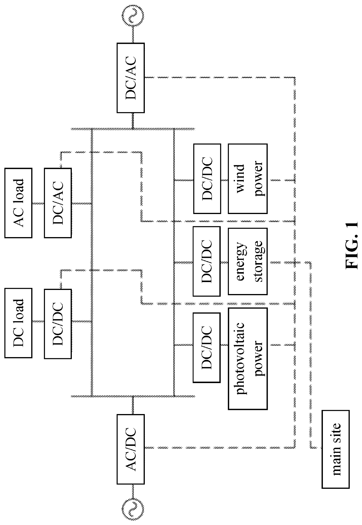
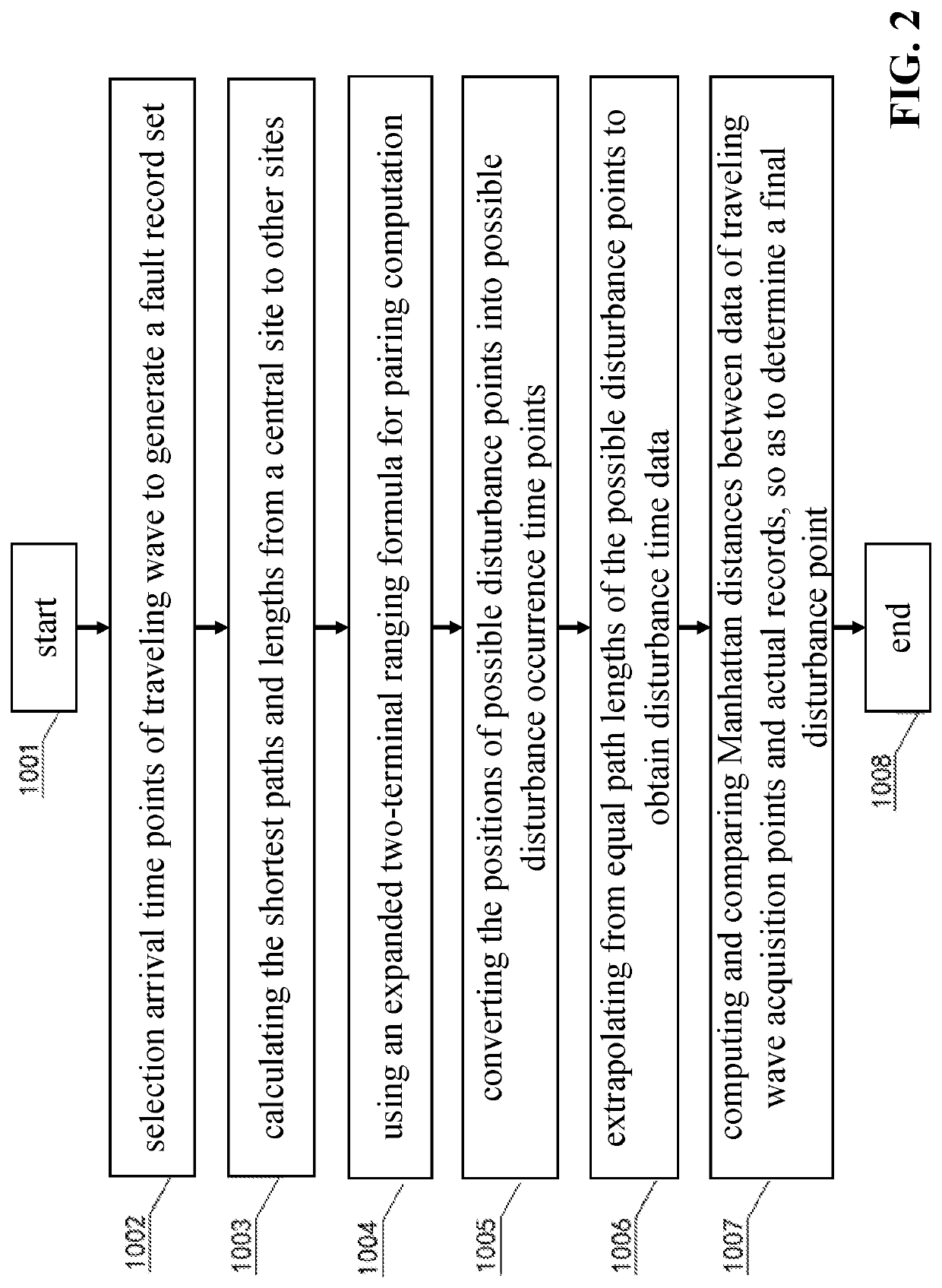
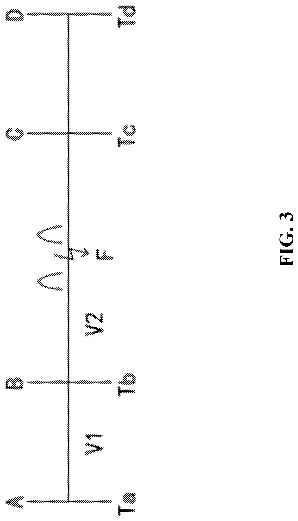
[0045]FIGS. 1-3 are the best embodiments of the present invention. The following are in combination with FIGS. 1-3 to further explain the present invention.

[0046]In a multi-terminal traveling wave fault ranging system of direct current (DC) distribution lines as shown in FIG. 1, alternating current (AC) transmission lines are connected to DC distribution lines via an AC-DC conversion system, and the DC distribution lines are also connected to AC distribution lines via a DC-AC conversion system. In the DC distribution lines, power is supplied to a DC load by connecting the DC-DC conversion system and the DC load. Also, power is supplied to an AC load by connecting the DC-AC conversion system and the AC load. A photovoltaic power generation system, an energy storage system, and a wind power generation system are also respectively connected to the DC distribution lines via the DC-DC conversion system, and DC power generated by electric power generation is fed into the DC distribution l...


PUM


Abstract

A method for fault location to multi-terminal traveling wave in a direct current distribution line, which belongs to the field of power line fault ranging and location technology. The method includes a main site and a plurality of acquisition points installed into the distribution line and includes steps as follows. Step 1001: collecting and uploading a traveling wave signal by each of the acquisition points after a fault occurs in the line; step 1002: generating a fault record set; step 1003: computing the shortest paths from a central site to other sites and their lengths; step 1004: using expanded two-terminal traveling wave ranging principle for pairing computation; step 1005: converting positions of possible disturbance points into possible disturbance occurrence time points; step 1006: extrapolating from equal path lengths of the possible disturbance points to obtain disturbance time data; and step 1007: determining a final disturbance point.

Description

CROSS-REFERENCES TO RELATED APPLICATIONS[0001]This application claims priority to the Chinese patent application No. 201911165839.X filed on Nov. 25, 2019, and the disclosures of which are incorporated herein by reference in their entirety.FIELD OF THE INVENTION[0002]The invention relates to a method for fault location to multi-terminal traveling wave in a direct current distribution line, which belongs to the field of power line fault ranging and location technology.BACKGROUND OF THE INVENTION[0003]With the development of power-and-electronic technology, direct current (DC) distribution line is more efficient than alternating current (AC) distribution line when it is connected to a distributed power supply to supply a DC load. Accordingly, technology in DC distribution networks and applications thereof have attracted attention, and distribution networks in the future will become hybrid distribution networks constructed by AC and DC distribution lines. When AC-and-DC hybrid distribu...

Claims


Application Information

Patent Timeline
Patent Type & Authority Patents(United States)
IPC IPC(8): G01R31/08G01R31/11
CPCG01R31/085G01R31/088G01R31/11G01R31/086
Inventor CHEN, YUWANG, JINGHUAXU, BINGYINPENG, KEWANG, WEI
Owner SHANDONG UNIV OF TECH
Learn More